|
Very early valves developed by the company are typified by the R2 and R5 types. The latter is a hand made example of a De Forest triode the original three electrode valve.
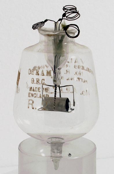 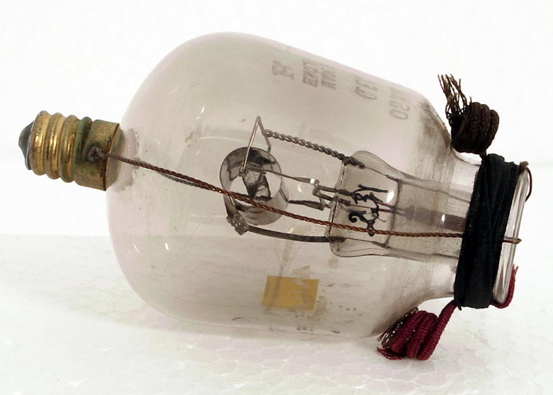
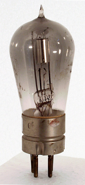
In 1918 only one type of receiving valve could be purchased by the experimenter. This was the 'R' valve, a general purpose triode. 30 years on it could have been regarded as a pretty poor thing; but to those who used it after the Great War it was wonderful. And they achieved astonishing results, receiving morse and voice transmissions over what were then almost incredible distances.
The 'R' type required 2.8 Watts to heat it's pure tungsten filament to the temperature needed to produce an adequate emission of electrons and, incidentally, a bright white glow (2,400°C). It was usually operated from a 6 Volt accumulator LT battery, each valve in a receiving set having it's own controlling rheostat.
In the 'R' valve the mutual conductance was only 0.225 mA/V. 30 years later not many receiving valves had a mutual conductance of less than 1 mA/V. in some it runs into double figures.
Despite all this the 'R' valve worked well, and as new circuits were developed, did things that had never been done before. But the Research Departments were very conscious of it's limitations, and efforts were soon made to effect improvements. Many of these were made during the first World War, but the valves which incorporated them did not become available to the public until later.
For one thing, these early valves were not very satisfactory as high-frequency amplifiers. The main reason for this was the comparatively large capacitances that existed between electrodes.
A capacitance provides a path for oscillating current; the higher the frequency the easier the path for a given value of capacitance. In a high-frequency amplifying valve, inter-electrode capacitances, especially those between anode and control grid, are of great importance. To be efficient, such an amplifier must have both grid and anode circuits sharply tuned. When this was done with and 'R' valve the feed-back of energy from anode circuit to grid circuit made the arrangement unstable and liable to oscillate. The valve had to be 'held-down' by the deliberate introduction of damping, with the result that only a small fraction of the HF amplification theoretically possible could be obtained in practice.
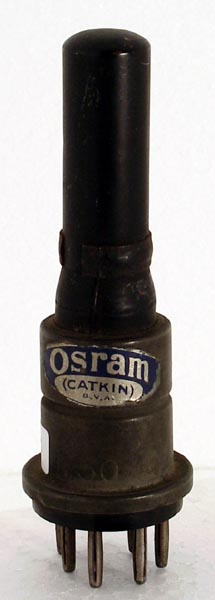
Obviously it was essential to reduce inter-electrode capacitances to a minimum, and the first promising step was the production of 'test-tube' valves of the V24 and QX types. These had four small metal caps, one at each end of the tube and one at either side.
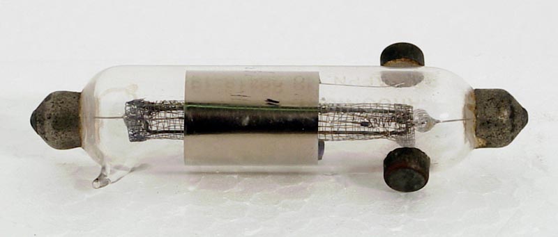
By specially shaping the anode, grid and filament and by bringing their leads to widely separated caps the inter-electrode capacitances were very considerably reduced and much more efficient HF amplifiers became possible.
The greatest step forward, however, was made when GEC introduced into this country the first practical form of screen grid valve, or tetrode. In this valve, anode-grid capacitance was cut down to an almost negligible figure. The valve had a very high amplification factor and for the first time full advantage could be taken of this by sharply tuning anode and grid circuits. By using screened tetrodes in cascade, a stable HF amplification approaching the million fold became possible.
Most of the high frequency amplifying valves of 30 years later are based on these early screened-grid valves.
Later a fifth electrode was added to the valve and the tetrode became a pentode.
The latter made it's first appearance as an audio-frequency amplifier; but it was not long before the RF pentode was developed and these two forms of the pentode made it possible to obtain enormous amplification from a comparatively small number of valves in cascade.
With the growing usefulness of shorter and shorter waves, corresponding to higher and higher frequencies, further reductions of stray capacitances have been needed. Osram valves kept their position in the van of progress by the introduction of 'planar electrode' and other types of low-capacitance, high efficiency valves, the successful development of which made communication on centimetric wavelengths possible. Also the development of radio links for television, of which the London-Birmingham Television Link, designed, made and installed by GEC was an excellent example.
As mentioned earlier, the first radio valves were all bright-emitters; that is, their filaments had to be run at a temperature sufficient to make them white-hot (2,400°C) in order to ensure sufficient emission of electrons. The bright emitter valve, however, was uneconomical in two ways.
First a current of 0.7 Amps to 1.5 Amps had to be supplied by a 6 Volt accumulator battery. Even a 60 Amp Hour battery gave comparatively short service for each charge. Taking into account the cost per recharge and the depreciation of the battery, the provision of LT current, which served no direct radio purpose and was used merely to raise the filament to a satisfactory electron-emitting temperature, was a very expensive item.
Secondly, the fact that the filament was working at a high temperature meant that it's life (and therefore the life of the valve) was comparatively short.
The task which designers of Osram valves set themselves was to produce an efficient and durable filament which could be heated economically from an accumulator. The ideal was a valve which could be operated from a single secondary cell.
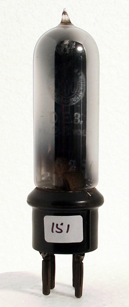
The problem was solved in a remarkably short time and almost immediately following the commencement of the BBC services GEC gave to the world a sensational valve, combining new ideas in economy of running with remarkably long life. This was the Osram DER; the initials stood for Dull Emitter Receiving. The filament was a thoriated tungsten wire that gave effective electron emission at 1,700°C.
The great advantage of the DER valve was that it only required 0.35 Amps of filament current at 1.8 Volts. Taking into account the 0.2 Volt wasted across the rheostat, the filament consumption was thus only 0.7 Watts, compared with 4.2 Watts of an 'R' valve run from a 6 Volt accumulator with series resistance.
This was revolutionary; but it was only a beginning and the manufacturers of Osram valves continued to introduce improvements in emission efficiency and reliability of low temperature cathodes. This development process included the Barium vapour (Azide) method of depositing Barium oxide onto the filament and finally resulted in the oxide spray coating process.
30 years on, a 4-valve battery-operated super-heterodyne receiver equipped with Osram valves could draw it's filament current economically from one small dry cell. The total drain need not exceed 0.25 Amps at 1.4 Volts, equivalent to 0.35 Watt. Compare this with the 2.8 Watts required by one of the original 'R' valves.
It has already been stated why a special type of valve was needed for effective HF amplification but it was soon found that the forward march of radio demanded the evolution of several other kinds of valve, each designed to do one job really well.
The general-purpose valves used in the output stages of early radio receivers caused distortions to music and speech, to which was added distortion by the loudspeaker with a final result which would be found intolerable 30 years on.
The loudspeaker is a current-operated instrument band power (Watts, not just Volts) is required to move the cone by means of which the sound waves are set up. It was therefore soon realised that if loudspeaker reproduction was ever to be anything like a faithful replica of the original sounds in the studio, a valve was needed which would convert large voltage changes in its grid circuit into considerable power changes in its anode circuit without linear loss.
One of the first power valves to be evolved for this purpose was an Osram bright-emitter triode, which appeared in 1925. It worked fairly well, though it was expensive to operate, for its filament drew 1.5 Amps at from 5.5 to 6 Volts and it was not really at it's best unless the anode voltage was at least 500 volts.
More efficient types followed one another with almost bewildering rapidity.(DE6).
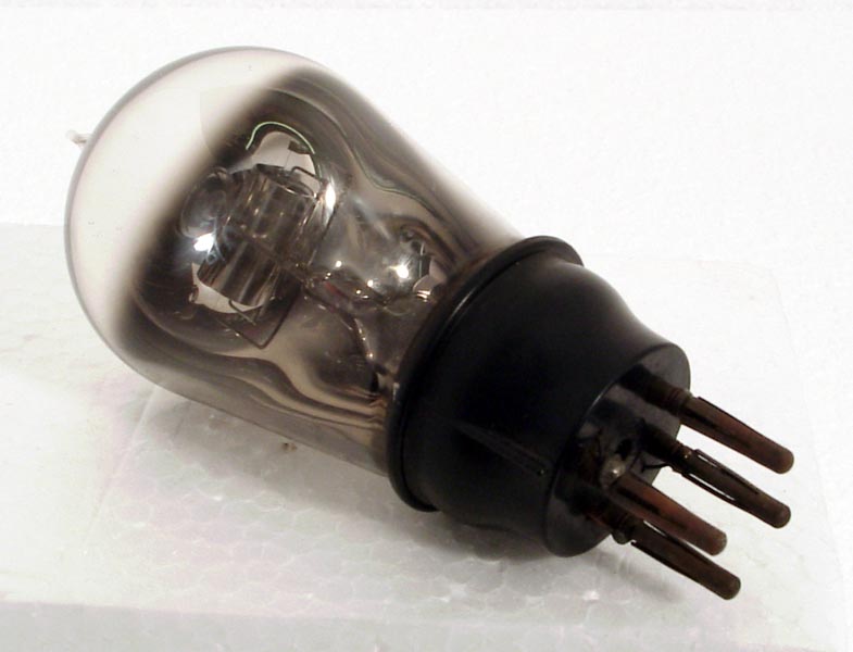
One such valve was the well-known LS5, a truly outstanding power valve of it's day, with a remarkable record of reliability and life.
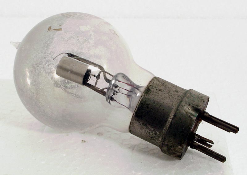
So far, we have considered only battery-operated valves. The reason is that no other kind was known during the early years of radio history. One very important consideration was that if means could be found of contriving an indirectly-heated cathode, the whole of it's surface could be maintained at the same potential. This cannot be done in directly-heated valves, for a potential gradient must exist from one end of the filament to the other.
Many attempts were made to produce indirectly-heated valves; but the first practical commercial type was introduced by GEC in 1925/26. This was the KL1, a radiation heated triode (produced in early 1927). From that time onwards progress was continuous and rapid. Like their battery counterparts, the Osram mains valves of 1950 were second to none for their efficiency, reliability, freedom from noise, economical operation and long life.
As radio has expanded into the realm of higher frequencies with the development of of television and Radar, many specialised Osram valves have been designed. To these have been added a wide range of GEC electronic devices, including various kinds of cathode ray tubes and photoelectric cells, gas filled rectifiers and Geiger-Muller tubes; all to serve the needs of science and industry, as well as the requirements of broadcasting, television and the many amateur transmitting enthusiasts throughout the world.
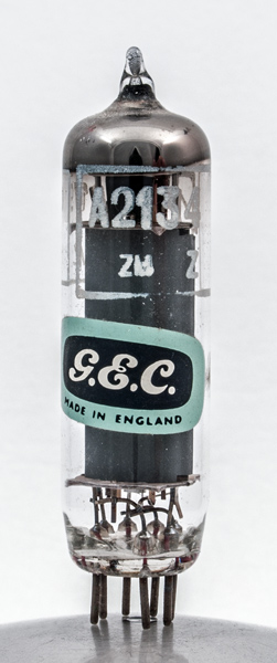
From the point of view of receiving valves, however, the most spectacular modern development has been the successful large-scale manufacture of 'all-glass' valves. This development makes possible the miniature valves which are so widely used in domestic receivers.
This was written in the early 1960's
|