|
The A C Cossor Limited company was among the first entrants into the field of valve manufacture in Britain. Very early in its history, Cossor produced X-ray and cathode-ray tubes, and were also responsible for the assembly of diode valves for use by Ambrose Fleming. Established as a private company in 1909, A C Cossor was one of only three British companies producing valves prior to the Great War, during which they manufactured the standard R-type valves.
By 1918 Cossor were well established and had set up a major valve manufacturing plant in Highbury Grove, North London. In 1924, Cossor was one of the founder members of the Valve Manufacturers Association, which by 1926 had become the nucleus of the British Valve Manufacturers Association (BVA).
Bright-emitter types: P1, P2
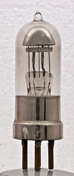 
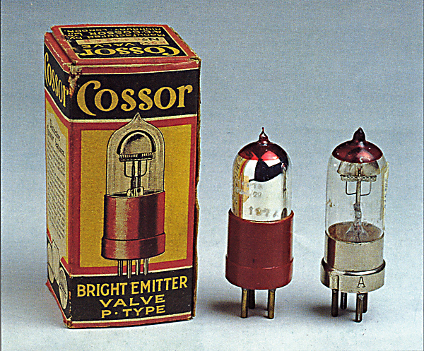
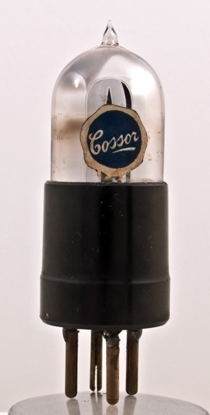
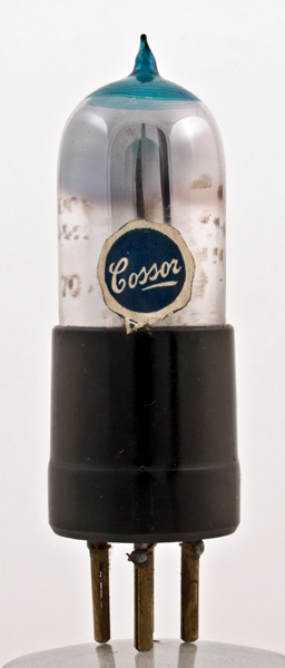
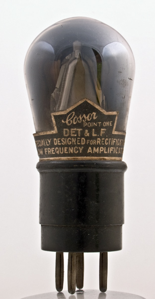
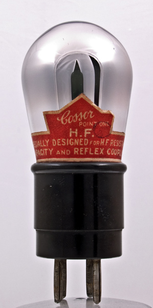
Early Cossor P1 and P2 bright emitter triodes
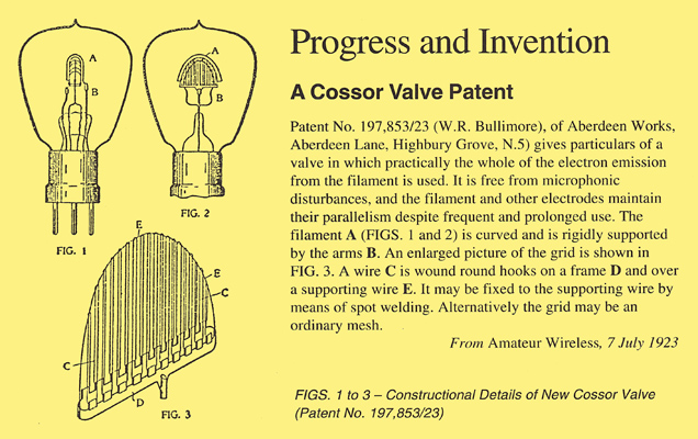
Cossor continued production of the wartime R-type until 1922, when they introduced a completely new valve of their own design, known as the P1. In anticipation of possible patent infringement problems over valve design with the Marconi Company, Cossor made a radical departure from the prevalent electrode construction of a spiral grid and a straight filament enclosed by a cylindrical anode. The electrode construction of the P1 valve was described in British Patent No 197,853/23 granted to W R Bullimore, and featured an arched filament combined with a distinctive hood-shaped grid and anode configuration.
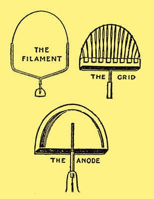
Electrode structure of the Cossor 'tin hat' types
The new P1 valve was soon affectionately known as the 'tin-hat' design, taking its nickname from the resemblance of the dome-like anode to the steel helmet used by the British army in the Great War. Much advertisement press was built around the unique design and rather extravagant claims regarding its efficiency were made. For example, Cossor asserted that the design permitted exceptional amplification factor because' ...the hood- shaped grid and anode- in conjunction with its curved filament -make use of practically the whole of the electron stream. None can escape to the sides of the glass. ...Further, the arrangement was considered to be particularly free of microphonic effects since' ...its grid is hood-shaped robust and immensely rigid with every turn anchored in three places. Parallels were even drawn between the life of the curved filament and the longevity of Roman arch construction!
(Evidently Bullimore - who became managing director of Cossor - had been considering for some time the question of alternative electrode design and the possibility of making more efficient use of the electron emission, since an earlier patent specification ( 192,464 ) applied for in 1921, described an unusual' ...spherical or egg-shaped filament enclosed in a similarly grid and anode in order to utilise fully the electron emission. ....
Illustrating the spherical electrode from patent No. 192.464 issue to W R Bullimore.
(Source: Wireless Weekly, 18 April 1924)
This design, however, must undoubtedly have presented manufacturing complexities and apparently was dropped in favour of the construction introduced with the P1).
Originally intended as a general purpose type, the P1 was later (after the introduction of the P2 -see below) advertised as principally suited for either rectification or low-frequency amplification. In a test report conducted by Amateur Wireless for 17 March 1923, the P1 was considered to be better suited to rectification than other general purpose types because of its open grid structure and low impedance. The evaluation was complimentary and the P1 was described as '... a first-rate low-frequency amplifier with a plate voltage rather higher than the normal 20-30 specified by the makers'. A later test conducted by Wireless World for 22 October 1924 suggested that good low-frequency amplification required an anode potential of 80 volts and a grid bias of -1.5 to -2.0 volts. Characteristic curves for the P1 are reproduced below.
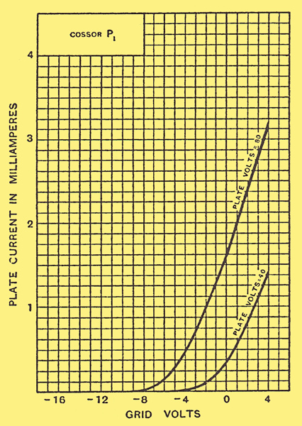
Characteristic curves of the Cossor P1.
(Source Wireless World, 22 October 1924)
A summary of the operating characteristics of the P1 is given in Table 1. As can be seen from the table, the characteristics are actually not significantly different from other 'general purpose' valves of the period, and in particular the amplification factor is quite unremarkable, despite the claims made for the new electrode structure.
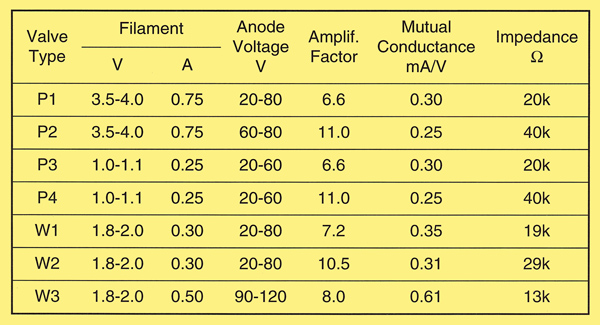
Table 1. Operating characteristics of early Cossor Types
P1, P2, P3, P4, W1, W2 & W3
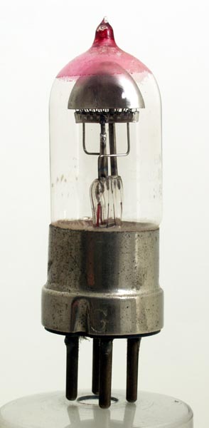
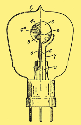
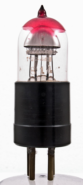
The Cossor P2, Shown in Fig. 4, was introduced in August 1923 and was intended for use as a high-frequency amplifier. Outwardly similar to the P1, the P2 was identified by a red marking around the top of the glass envelope. Parenthetically, Stokes 1 points out that Cossor was actually the first British valve maker to use a colour coding scheme.
The general design of the P2 followed that of the P1, except that the grid was slightly modified and the grid-filament distance was altered. Operating characteristics can be compared with the P1 in Table 1.
The P2 was the subject of a detailed evaluation in the 4 August 1923 edition of Amateur Wireless which described the valve as an' ...extremely efficient radio-frequency amplifier, robustly made, and not over-exacting in its demands upon the accumulator'. It was found, however, that a filament potential of 4.5 volts was required for reasonable emission -somewhat higher than the rated value. Another criticism was the grid current which at 0.17 μA with zero volts on the grid, was considered 'on the high side'.
According to the later Wireless World tests, the filament emission characteristics of the P2 were almost identical to the P1 with both exhibiting adequate emission at maximum rated voltage. An anode potential of 50 volts was found to give good results as a high-frequency amplifier. Representative characteristic curves of the P2 are shown in Fig. 5.
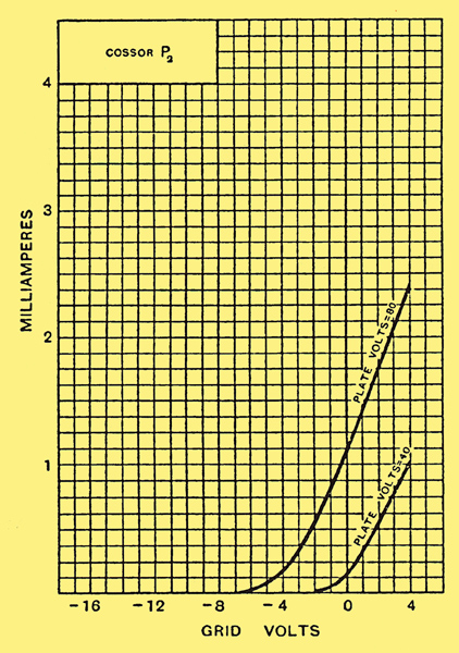
Characteristic curves of the Cossor P2.
(Source Wireless World, 22 October 1924)
Dull-emitter types: P3, P4
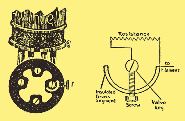
A dull-emitter type using the same 'tin-hat' electrode configuration as the P1 and P2 valves, is known to have been advertised as early as November 1923, and was shown for the first time at the AII-British Wireless Exhibition at the White City, London in the same month. In some advertisements, the new dull-emitter- designed to be powered from a single dry battery -was referred to as the 'Wuncell'; the name, of course, denoting one-cell operation. This valve apparently was intended to be operated at a filament potential of only 0.8 V with a current rating of 0.22 A, claimed to be the lowest power consumption of any valve on the market.
By the end of the year, two dull emitter types, the P3 (low-frequency amplifier, or detector) and P4 (high-frequency amplifier) were advertised. These were identified by a green and blue top respectively, and were essentially low-voltage equivalents of the P1 and P2 (see Table 1). The filament rating was increased slightly to 0.25 A at 1 to 1.1 V.
The P3 and P4 seem to have been short-lived and were no doubt made obsolete by the introduction of the more well-known 'W'-series 'Wuncell' type dull emitters described below.
The Wuncell range
Early Cossor W1, W2, W3 and WR1 dull emitter triodes
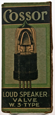
On 1 October 1924, according to advertisements in Popular Wireless, a new range of Wuncell types was released to dealers: the W1 -corresponding to the P1, for detector and low-frequency amplifier use; the W2 -the P2 equivalent, for high-frequency amplification; and the W3 -a new power type intended for loudspeaker amplification.
The Wuncell valves were designed to operate from a single accumulator - the W1 and W2 being rated at 0.3 A and the W3 rated at 0.5 A filament current.
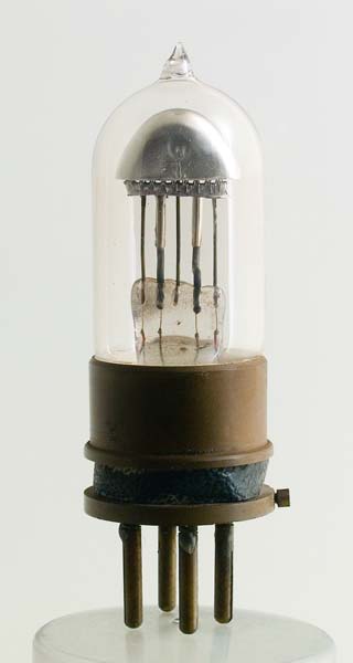
The W2 and W3 were identified by a red and green top, respectively. Despite the 1924 Popular Wireless advertisement, the W3 does not seem to have been generally made available until the following year (see Note). Although it employed an arched filament and a dome-shaped grid and anode, the actual electrode structures employed in the W3 differed from the previous 'tin-hat' types.
Wuncell type W3 dull emitter. Note the modification to the anode geometry
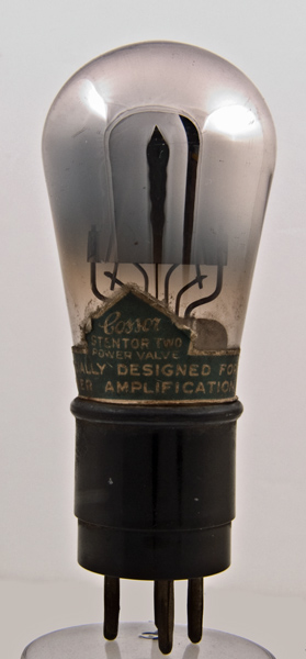
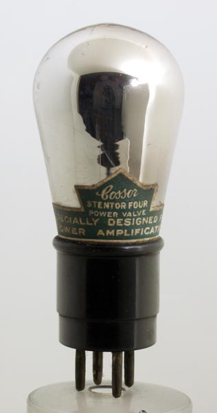
This new electrode design was later adopted for the Cossor 'Point One' and 'stentor Two' valves introduced in 1926.
In the Wuncell, Cossor provided an exclusive, patented feature whereby the valve could be operated alongside bright-emitter types, using the same 4 V or 6 V accumulator, thus facilitating a user's transition from bright to dull-emitters in multi-valve sets, without incurring the expense of replacing all of the valves at the same time. A resistance connected in series with the filament was concealed in the base of the Wuncell and a milled thumbscrew could be inserted in one of two threaded holes in the base. When screwed into the one marked 4-6 V, the resistance was unaffected, allowing the valve to be powered by the higher voltage accumulator. However, when the need arose to use a single accumulator, the resistance could be rendered inactive by inserting the thumbscrew into the hole marked 2 V, in which it made electrical contact with one of the filament pins and short-circuited the resistance.
The Wuncell WR1 and WR2 featured a resistance in the base enabling the valve to be used with either a 2-Volt or 4-6 Volt accumulator
At the end of October, shortly after they were announced, the W1 and W2 were renamed WR1 and WR2 (R for resistance) and new versions of the W1 and W2, without the resistance in the base, and designed for 1.8 to 2.0 Volts, were advertised. The W3, released later, seems to have only been produced in the standard type (ie with no resistance in the base), and no record of a WR3 appears to exist.
Extensive testing of the Wuncell range was reported in Wireless World for 28 October 1925. For the W1, when used in the first stage of an audio frequency amplifier, an anode potential of 100 V and a grid bias of -2 V was recommended. The W3 was considered as capable of good results in the last stage of a power amplifier and, with 120 V on the anode and -5 V applied to the grid, was judged to give sufficient power to operate a loudspeaker quite comfortably.
Cossor packaging and pricing
See P1 box, P2 box, W1 box, W2 box & W3 box.
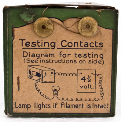
With the introduction of the Wuncell family, a new packaging approach was also instituted, allowing dealers to demonstrate that the filament was intact, without having to break the seal on the carton. Each valve was packed with two wires attached to the filament pins carried through the packing and fastened to two contacts on the outside of the box. When the box was placed in contact with a specially designed show-card supplied by Cossor to dealers, a small light bulb was illuminated if the valve filament was in good condition. In this way customers were assured of purchasing a tested valve which was new and unused.
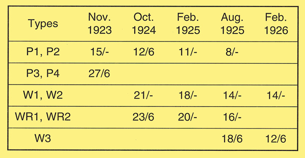
Price comparison of early Cossor valves
(Source: Wireless World, Amateur Wireless, Wireless Constructor, Popular Wireless)
Prices in shillings/pence. One shilling = 12d (old money) = 5p (new money post 1971)
A summary of Cossor pricing for the tin-hat valve range is provided above. The dull-emitter types were significantly more expensive than the earlier bright-emitters, as was typical for valves of this period. Like other suppliers, Cossor were forced to reduce their prices substantially during the early production years in the face of increasing competition.
The Cossor Point One and Stentor Two valves utilising the modified electrode structure of the W3 and featuring the new 'Kalenised' filaments superseded the Wuncell range in 1926. These filaments operated at low temperature and were advertised to give exceptionally long life.
Despite a number of mergers and take-overs during the 1920s and '30s, A C Cossor continued as a successful valve manufacturer for three decades, finally exiting the business in 1949, with the sale of their valve operation to EMI Limited (Electrical and Musical Industries).
Note
There seems to be some confusion over the actual date of introduction of the various Wuncell types, complicated no doubt by the changes in the names of the different types. For example, Thrower [2] Keith R Thrower, History of the British Radio Valve to 1940. (1992). gives 1925 as the date for the W3 although it was certainly advertised earlier. The original Wuncell, although advertised in Wireless World as early as November 1923, was not widely advertised elsewhere; The W1, W2 and W3 appear in Popular Wireless advertisements commencing in September 1924. Tyne however, cites an advertisement in Amateur Wireless for July 1925 as the introduction date of the W3.
Further confusion arises over the P3 and P4. Tyne [3] Gerald F J Tyne, Saga of the Vacuum Tube. Published by Howard W Sams & Co, Inc, Indianapolis (1987), (2nd printing). gives 1924 as the introduction date, but they are known to have been advertised in 1923 by A J Dew & Company of London. The situation is further complicated by the introduction in 1925 of a second P3 (green top) type with quite different characteristics from the earlier one. The later P3 is listed by Thrower (page 157), and was an audio output valve with a filament rating of 0.2 A at 4.0 to 4.5 V.
References
- John W Stokes, 70 Years of Radio Tubes and Valves. Published by the Vestal Press, New York (1982).
- Keith R Thrower, History of the British Radio Valve to 19401004. (1992).
- Gerald F J Tyne, Saga of the Vacuum Tube. Published by Howard W Sams & Co, Inc, Indianapolis (1987), (2nd printing).
- 'Finding the Best Valve', Amateur Wireless, Vol. 2, No.41, (17 March 1923) p.322.
- 'Abstracts from Full Patent Specifications Recently Published', Wireless Weekly, Vol. 1, No.2 (18 April 1923): p.122.
- 'P2 -The Pink Top Cossor', Amateur Wireless, Vol. 3, No.61, (4 August 1923): pp.124-6.
- 'Wireless Apparatus & Accessories', Catalogue by A J Dew and Company, Endell St, London, (November 1923): p.83.
- 'Valve Tests -The Cossor P1 and P2, Wireless World, Vol. 15, No.4, (22 October 1924).
- 'Valves We Have Tested -The Cossor Series', Wireless World, Vol. 17, No.18, (28 October 1925): pp.577-9.
|