|
Mullard
In the very early days of radio valve production, most valve filaments were short, straight wires of pure tungsten, and the grids and anodes were of the most obvious form - cylindrical.
Even at this stage, however, it was realized that if the filament length could be increased, with a corresponding increase in effective length of grid and anode, a super valve would be produced capable of exceptional performance. Unfortunately, the filament length for a reasonable filament voltage and current was limited by the material of which the filament was made.
With the advent, though, of the dull emitter filament, materials other than pure tungsten enabled the length to be increased, so much that the cylindrical construction was superseded by the flat or so-called elliptical type of grid and anode. Even with this improvement the most that could be done with a thoriated tungsten filament was to make a single loop.
The PM Series
See also The Philips-Mullard (PM) Series & Mullard.
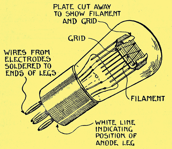
Fig. 1 - Diagram showing the general assembly of a Mullard PM valve.
In the PM series of valves, manufactured by the Mullard Radio Valve Company, the filament has as many as four limbs, thus providing up to three times the normal length of filament, with a corresponding increase in performance. Fig. 1. shows the general PM construction.
The amount of electron emission from such a filament as the PM is greatest from the centre portion of each limb and decreases towards the ends, somewhat as shown in Fig. 2.
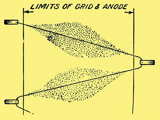
Fig. 2 -The form taken by the emission from a Mullard PM filament. (It is greatest from the middle part of each limb).
If the centre portions of the filament are well covered by the grid, few electrons will be able to pass from the filament to the anode without coming under the influence of the grid.
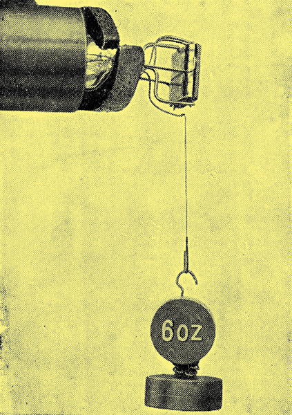
Fig. 3 - Mullard PM filament after 1,000 hours use carrying a load of 6 oz in tension.
For efficient working and in order that a valve will maintain its electrical characteristics at a constant value throughout its life, it is most important that the electrodes (grid, plate, and filament) should be incapable of moving relatively to one another. With the old system, in which all the electrodes are supported at the far end of the soft nickel rods secured into the glass pinch at one end, there is a danger that the whole system will bend over. This weakness is overcome in the PM valves by mounting the electrodes horizontally. Both grid and anode are held rigidly and independently at both ends by short supports of hard nickel alloy. The rigidity and strength of the PM assembly are well illustrated by Figs. 3 and 4, which are photographs of standard assemblies.
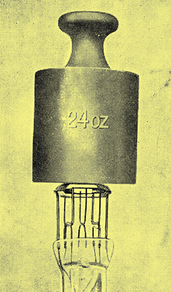
Fig. 4 - Assembly of Mullard PM valve carrying a load of 24 oz compression without mechanical distortion.
In Fig. 4 the anode is seen carrying a load of 24 oz. In Fig. 2 the filament of a PM valve which has been run for 1,000 hours is seen carrying a load of 6 oz. One filament support was merely detached from its glass foot and attached to the load, thus the filament which is taking the whole of the load is shown to be strong and ductile. After the equivalent of about 2,000 hours normal use a PM filament can be knotted as shown in Fig. 5.
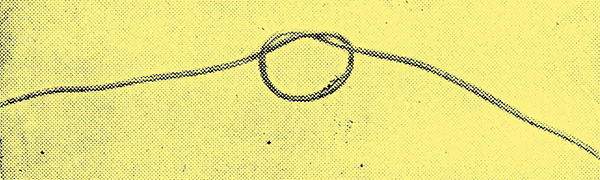
Fig. 5 - Mullard PM filament (enlarged) knotted after 2,000 hours use.
The filament of a valve will expand when heated to an extent depending upon the temperature. which in the case of the PM is so low that no sign of glow can be discerned. In addition, the filament is set around strong resilient hooks in a special way, so that it is entirely free from possibility of displacement during the long life of the valve. This effectively avoids the sagging of the filament towards the grid.
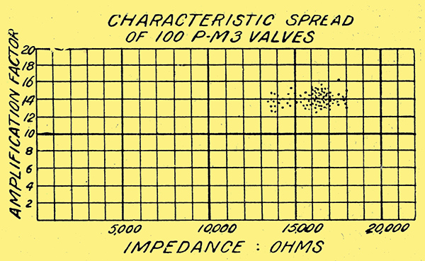
Fig. 6.
The uniformity of characteristics yielded by the application of the above mentioned principles to the manufacture of the PM valve is well illustrated by the target diagram (Fig. 6). These are the test results of a batch of valves taken quite at random from stock, and it is seen how closely the individual valves cluster around the standard values of amplification factor and impedance to which the valves are made. This uniformity of characteristics is, of course, of great value when valves are required for super-heterodyne and similar sets, where formerly valves had to be specially matched.
Choice of Valves
There seems to be considerable doubt amongst amateurs as to what type of valve he should use for a particular purpose. One hears that such and such a valve, which is really intended for high-frequency amplification, gives excellent results as a low-frequency amplifier, and in some cases it does, but not in all cases. This is apt to be confusing, and the following advice should help to clear matters up.
There is no need from a safety point of view, to use filament resistances with any of the PM valves, provided that the requisite accumulator be used (2, 4, or 6 Volts).
For high-frequency amplification. Class B will give the best results, that is when the usual standard methods of coupling are employed. It must be remembered that the impedance of the valve used should bear a definite ratio to the impedance of the apparatus used in its anode circuit. For instance, when using certain types of American high-frequency transformers, the primary impedance of which are low, better results are often obtained by means of Class C valves. Most British apparatus, however, is designed for use with Class B valves.
For detection, the same valves are usually found most suitable, although here again the external anode impedance is of importance. For example, Class A should be used if the following valve is resistance coupled, but Class B if transformer coupled. (Most low-frequency transformers have a comparatively low primary impedance.)
For low-frequency amplification we have to bear in mind another factor - grid bias. The grid bias of a valve is the projected length of the straight portion of the characteristic curve to the left of the zero grid volts line. A low-frequency valve will distort if its grid is made either positive or so negative that the working point is on a bend in its curve. If we apply a negative grid bias equal to half the total applied grid bias, we can handle all signals of an equivalent alternating voltage. If, however, we apply the amplified output from the same valve to the grid of a similar valve, the second valve will be badly overloaded. It can be readily seen, therefore, that a valve which is to be used in the last stage of an amplifier must have a very large grid bias or distortion is inevitable. Hence, the high amplification factor valves (Class A for choke or resistance capacity coupling, and Class B for transformer coupling) should be used for the first stage only, the next valve should be of Class B, while the output valve must be either a C or D, depending on the amplitude or loudness of the signal it is desired to handle.
To determine the approximate grid bias of a valve, the following is a useful rule:-
grid bias = Maximum high tension voltage / Amplification factor.
Valve impedance or internal resistance (Ra) is stated as being of so many Ohms. The value of this impedance in relation to the amplification factor (μ) is an all important ratio to consider when considering the suitability of certain valves for work required of them. Thus, if the amplification factor of a certain type of valve is 13 and its impedance is 16,000 Ω, the ratio μ:Ra is shown by the figures 13:16,000 or 13/16,000.
The following is a complete list of Mullard receiving and rectifying valves giving their characteristics.
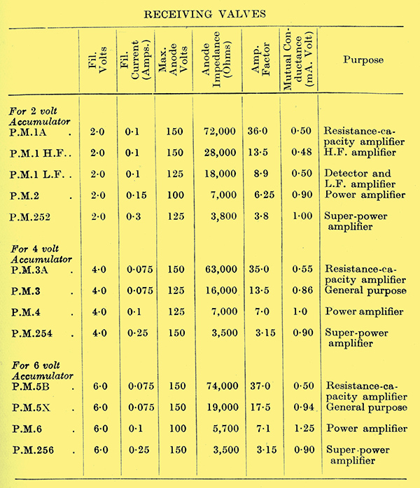
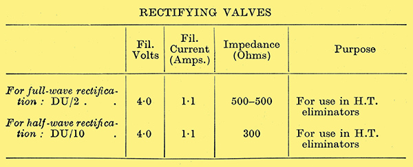
PM1A, PM1HF, PM1LF, PM2, PM252, PM3A, PM3, PM4, PM254, PM5B, PM5X, PM6, PM256, DU2 & DU10
BSA-Standard Valves
BSA-Standard Valves.
See also BSA-Standard.
In producing the series of BSA-Standard valves careful consideration has been given to practically every requirement of the valve user and a complete range of valves is available.
The special tape filament is durable, economical in use and gives silent and non-microphonic working.
The complete range of BSA-Standard valves consists of:-
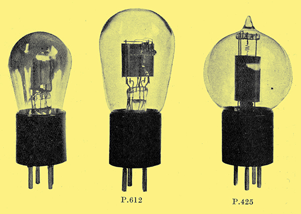
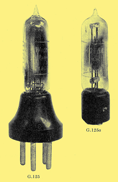
- G125 (1 Volt, 0.25 Amp.). General purpose.
- H125 (1 Volt, 0.25 Amp.). High-frequency and detector.
- G225 (2 Volt, 0.25 Amp.). General purpose.
- P425 (4 Volt, 0.25 Amp.). Power amplifier.
- P612 (6 Volt, 0.12 Amp.). Power amplifier.
G125, H125, G225, P425 & P612.
The G125, H125, and PA25 are also obtainable with bayonetfitting.
BSA-Standard Valves.
The New Screen-Grid Valves
Undoubtedly the most important advance in wireless valves recently has been the introduction of the screen-grid HF amplifying valve. The introduction of this valve, although primarily intended to increase the range of a wireless receiver, is doubly important in that at the same time it allows for a much higher quality loud speaker reproduction being obtained.
Let us see how this is possible. A wireless signal received on the aerial consists of a carrier wave of a certain defined frequency, depending upon the wavelength of the signal, and super-imposed on this carrier wave are the modulations of speech and music frequencies, which may vary from 50 up to 5,000 Hz. These super-imposed frequencies are commonly known as the side bands to the carrier wave.
If we take an ordinary receiving set consisting of a detector valve and one or two stages of low-frequency amplification, a certain signal voltage is received by the detector valve, the strength of which depends on the efficiency of the aerial system and the locality of the receiver with respect to the transmitting station. This input to the detector, together with the design of the low-frequency amplifier, decides the amount of volume output we can get from the loud speaker. It is very often desired to increase this volume output, particularly if the aerial is a bad one or the receiving signal is very weak, and this is commonly done by applying what, is known as reaction on the detector valve.
While this certainly increases the strength of signals, it only does so at the expense of the higher frequencies of the side bands; and the result is invariably a muffling of tone, due to the cutting out of the high musical frequencies.
The use of reaction, therefore, is bad if we want to obtain good quality reproduction and a natural clear tone. If, however, reaction is to be avoided, it is necessary that the signal be amplified before it reaches the detector valve, and this is done by means of a high-frequency amplifier.
Unfortunately, in the past, it has been extremely difficult, to obtain a high-frequency amplifier working with ordinary valves, which gives a high degree of radio frequency amplification without bursting into oscillation and becoming uncontrollable. The new screen-grid valve, particularly of the Osram S625 design, gets over these difficulties.
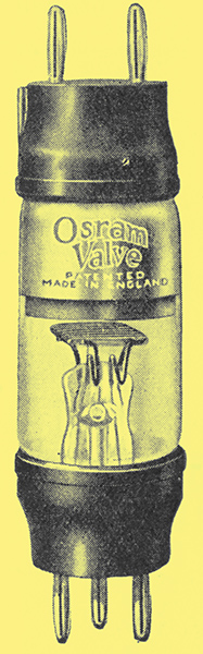
The GEC S625 Screened Grid Valve.
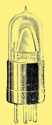
The Osram S625 is made in a tubular form with the filament and grid pins at one end, and the anode and screen-grid pins at the other. By this means, the input and output sides of the valve are entirely separated from each other, and the self-capacity of the valve (one of the most serious causes of losses and instability in HF amplifiers) is reduced to an extraordinarily low figure. The accompanying photograph shows the design of the S625 valve and in practice this is usually mounted in a horizontal position, so that the bulb fits in a slot or hole through a copper or aluminium screen which can be joined to the earth terminal of the set. By means of this design, 2 stages, or even 3, of HF amplification can be used without oscillation.
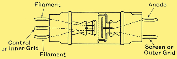
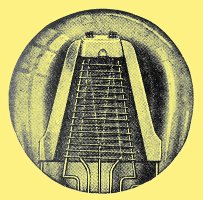
Diagram of the internal connections in the S625.
A second and very important advantage of the S625 screen grid valve is that the introduction of the second or screen grid produces characteristics which give a degree of amplification, which would be impossible in an ordinary valve.
By suitable voltages on the screen grid and anode the valve shows an amplification factor of about 110 for an impedance of Only about 200,000 Ω. In an ordinary valve for this high amplification factor the impedance would be about five or six times as great.
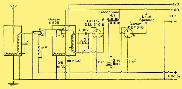
A home constructor's circuit diagram. this incorporates the S625 DEL610 and DEP610.
This high amplification factor combined with the comparatively low impedance enables the valve, in conjunction with a suitable circuit, to give perfectly stable amplification of up to 30 or 40 times per stage. Thus a 2-stage amplifier using the Osram S625 valve can easily be made to give a total high-frequency amplification of over 1,000 times. This enormous amplification thus maintains a very high quality of reproduction, and at the same time enables a simple set to be made up, capable of picking up a number of alternative programmes at loud speaker strength.
On an outdoor aerial the number of stations received depends only upon the atmospheric interference and general ether noises; there being adequate power available to receive the weakest possible signal that the ether conditions permit.
An anode bend detector valve, such as the Osram DEH610 is recommended, and this may be followed by one stage of resistance capacity coupling to a super-power valve of the Osram DE5A class, this being all that is necessary for full loud speaker strength and excellent quality.
Full particulars of the valve and circuits can be obtained from the makers, the General Electric Co, Ltd, Magnet House, Kingsway, WC2.
Cossor Valves
See also A C Cossor & The Early Cossor Tin-hat valves (1922-1925).
Cossor Point One valve.
The art of broadcasting was still very young when Messrs. A C Cossor, Ltd., first introduced their P1 and P2 type valves. The most unusual feature of these valves was the method of disposing the various electrodes.
Inside the hooded anode the grid was designed to follow the line of the anode construction, whilst inside the grid was placed the famous arched filament. This entirely new method, besides ensuring extreme stability of electrodes and strength of filament, made full use of the electron stream emitted. These P type valves proved to be extremely efficient, and became immediately popular. They functioned from a 4 Volt accumulator, and the filament consumption was 0.7 Amp. (in those days dull emitter valves being almost unheard of). The P1 and P2 valves remained the only type manufactured by Cossor until December, 1925, when valves of the Wuncell type were introduced. These new types, whilst following the usual Cossor method of construction, were fitted with a special filament, which, functioning from a 2 Volt accumulator, consumed only 0.3 Amp. As was expected, the advent of these new valves created great interest amongst wireless enthusiasts.
During this time the Cossor engineers were experimenting with a method of construction, and a new type of filament, to be embodied in a further and still better edition of Cossor valves. The result of their labours was seen in June, 1926, when the first of the Cossor Point One series was issued.
Cut-away view of the anode.
The illustration shows one of these valves with half the anode removed to show the unusual constructional features. The anode is an enlargement and an improvement of the original hooded type, whilst the construction and winding of the grid has been entirely revised. It is interesting to note that each turn of wire round the grid support is welded in two places - that is to say, to each support. This ensures that there shall be no movement of the grid coils which would set up microphonic and other undesirable noises in the valve when in use. The filament, as will be seen, is suspended at its apex by a very ingenious and unique method. A Seonite insulator is inserted in the apex of the anode, and through this insulator passes a tiny wire, the lower end of which is hooked, and the top portion of which forms a spring. It will be readily realized that such a device is calculated to absorb any shock to which the filament may be subjected, and also to maintain the filament taut and in its correct position in relation to the grid. This last point is important, as any variation in the position of the electrodes would materially alter the characteristics of the valve itself, but with this special construction no single electrode may be moved independently. If, due to severe handling, the anode is moved towards the side of the valve, the grid and filament accompany it, still in their correct relationship the one to the other. This special method of construction is exclusive to Cossor valves, and has proved its worth on innumerable occasions, especially where these valves are used in portable receivers.
The filament fitted to the first Point One valve took the form of an inverted V and this, through further experiments, was even further improved upon, when in March, 1927, Cossor introduced valves of the Point One series for use with a 6 Volt filament supply. These new 6 Volt type valves were immediately popular, and took their place in the front rank of valves for the higher voltage.
Almost simultaneous with the introduction of these 6 Volt Point One valves, Cossor introduced another valve of the 2 Volt series, which has done much to revolutionize methods of low-frequency amplification. Until this 2 Volt RC valve was issued with its comparatively low AC resistance, and high voltage amplification factor, it was a common belief that two stages of resistance capacity coupling were required to obtain the volume equal to one stage of transformer coupling. Receivers were constructed using these valves and giving stage for stage equal amplification and better quality of reproduction than receivers employing transformer coupling.
Having issued a complete range of 2 and 6 Volt types, a series designed on the lines of the 6 Volt valve was duly issued. These new Point One types, twelve in all, included valves to suit every requirement for either 2, 4, or 6 Volt accumulators, and each type was distinguished by a coloured band, red band for high frequency, black band for low frequency, blue band for RC, and green band for the Stentor type. In the 2 Volt series the black band valve is designed to function as detector or first stage of low frequency, whilst in the 4 and 6 Volt series the red band valve is designed to function as high frequency or detector. The whole range of these valves, as indicated by their title Point One consume only one-tenth of an Ampere filament current, with the exception of the Stentor Two power valve, which consumes 0.2 Amp.
It will, therefore, be readily seen that even with a seven-valve super-heterodyne receiver using Point One valves, the filament consumption of the whole is less than that of the old original P type. This extremely low consumption is a feature of the kalenized filament, a filament which, after having undergone a process known only to Cossor engineers, becomes the possessor of enormous emitting powers and marvellous tensile strength. This was proved very strikingly when twelve of these Point One valves chosen indiscriminately from stock were thrown individually from an aeroplane flying at a height of 500 ft.
Further additions to the range of valves mentioned in the preceding paragraph are the 230P super power valve of the 2 Volt type, specially designed to handle an extremely large grid swing, (that is, powerful signals), and eminently suitable for use in the last stage of multi-valve receivers. The second addition is the 610FP, also a valve in the power type, but as the initial letters indicate is primarily intended for use as a first power valve to precede the 610P super power valve. The 610FP is suitable for use in, say, a three-valve receiver as a last stage valve, and in five valve receivers of the Solodyne type is ideal as first low-frequency amplifier. In both these two new valves the specialized method of construction is adhered to, but the makers acquaint us of the advent of the SG210 valve which is a four-electrode valve of the screened-grid type. This valve is in a class of its own, and is specially designed to give extreme amplification of the weakest signals. It is, therefore, invaluable for DX work. A feature of this valve is the fitting of the screened grid in a rectangular space specially cut away from the plate between working grid and anode. This method of screening is, of course, much more efficient than the usual method of employing a complete disc composed of mesh to form the screening grid.
The Cosmos AC Valve
See also Cosmos.
The introduction of high-tension battery eliminators for supplying the voltage to the anodes of valves and in some cases to the grids for biasing, have not met with the popularity they deserved for the simple reason that the public felt that the solution of running a wireless set direct off the mains had been only half solved. It was appreciated that the avoidance of the continual testing and purchase of new high tension batteries three times per year was, indeed, a step forward, but the results obtained with these new eliminators on receivers previously operated on a steady source of potential, were not comparable from the point of view of dead silent background, complete elimination of all hum, and ability to react the set up to its most critical and sensitive condition.
The position was reached where only a partial solution was offered to the user for utilizing his electric light mains, and this partial solution had disadvantages which overbalanced the advantages. The operation of the receiver was not so good as with a new high tension battery, and, at the same time accumulators for the filaments of the valves had still to be used, and carried for charging or periodically called for by the local agent.
Many attempts had been made to run the filaments also direct from the mains by utilizing the valves already installed in the receiver, but the fact that accumulators were originally essential for heating the filaments, had caused valve manufacturers to develop valves of the lowest possible consumption in order that the user could operate his set off an accumulator for a longer time before recharging was necessary.
The consequence of this development tended to make the problem of accumulator elimination more difficult, from the fact that a small thin filament of small bulk can change in temperature more rapidly than a large thick filament of large bulk. If a varying voltage be applied to these filaments, the variations in actual temperature and, therefore, in emission will be less marked in the case of the thick filament valve. Therefore, direct running from mains to filaments of valves in everyday use would necessitate elaborate smoothing arrangements.
The solution of the whole problem of complete battery elimination lies in the development of the AC valve. From the previous remarks it will be appreciated that a bulky filament will require less smoothing, or, in other words, will not fluctuate so much in temperature even when supplied with alternating current.
The Cosmos AC valve consists of the usual anode and grid, but in place of the filament a glowing cathode is used. This cathode is indirectly heated by a heater filament requiring 1 Amp. at 4 Volts. The cathode, therefore, is kept at an even temperature, and, in consequence, its emission remains constant. No smoothing is necessary, and the mains supply is connected direct on to the heater filament after being transformed down to 4 Volts.
The introduction of the Cosmos AC valve, therefore, forms the final solution of the wireless receiver operated direct off the mains. At the same time that the robust and large cathode of the Cosmos AC valve compensates for the supply fluctuations, the large cathode with resulting emission produces a valve of larger output and greater sensitivity than valves developed to operate on the lowest filament current in order to reduce the necessity for the continual recharging of accumulators.
The net result of the introduction of the Cosmos AC valve not only solves complete battery elimination, but simultaneously considerably improves the sensitivity of the set and the resulting output from the loudspeaker before distortion is noticeable.
|