|
Schmitt Phase Inverter
We complete our examination of phase-splitters by describing the Schmitt phase inverter.
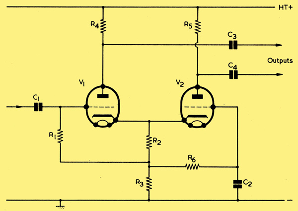
The Schmitt phase inverter.
A further type of phase-splitter, commonly referred to as the Schmitt phase inverter, is illustrated. In this diagram we have two similar triodes (which may, in practice, consist of a double-triode) sharing the common cathode resistors R2 and R3. R2 functions as a common cathode bias resistor and, because it passes the cathode current of both valves, has half the value which would be used by either triode operating as a voltage amplifier on its own. Bias is applied to the grid of V1 by way of R1 and to the grid of V2 by way of R6. These two resistors may have values of the order of 1MΩ. The lower cathode resistor, R3, has a much higher value than R2 and may be, typically, 20kΩ or more.
Resistors R4 and R5 are nominally equal in value and form the anode loads for V1 and V2. They may have the values normally provided as anode loads for these valves when working as voltage amplifiers. C1, C3 and C4 are AF coupling capacitors. C2 has a low reactance at audio frequencies and could be, typically, 0.1μF.
If a positive-going input signal is applied via C1 to the grid of V1 this valve draws greater current, with a consequent increased voltage drop across R4, and across R2 plus R3. Thus, the anode goes negative (providing one of the output signals) whilst the cathode goes positive.
Since the cathode of V1 connects to the cathode of V2, the latter goes positive also. At the same time, the potential on V2 grid remains fixed, due to the presence of C2. A cathode going positive relative to its control grid has the same effect as a control grid going negative relative to its cathode, and so the positive excursion of V2 cathode results in a reduction of anode current in this valve. Less voltage is therefore dropped across R5 and the anode of V2 goes positive, thereby providing the second output signal.
We have seen, then, that by applying a positive-going signal to the grid of V1 we obtain a negative-going output signal at the anode of V1 and a positive-going output signal at the anode of V2. Similar reasoning will demonstrate that a negative-going input signal results in a positive-going output signal from V1 and a negative-going output signal from V2. The circuit provides, in consequence, two out-of- phase outputs and so meets the first requirement of a phase-splitter.
The two outputs will have very nearly equal amplitudes if the triodes have a high amplification factor and if R3 has a high value of resistance. In practice, an ECC83 would represent a good choice for V1 and V2, and R3 should have a value of the order just mentioned., When R4 and R5 have exactly equal values the output from V2 anode is always slightly lower than that from V1 anode. The amplitudes can be balanced in practice by making R5 some 2% to 4% greater than R4.
Although the cathodes have an un-bypassed cathode resistor, there is not the same heavy degeneration as occurs with the split-load phase-splitter because, in this case, almost equal currents of opposite phase flow in the resistor. The gain offered by the circuit for either output is, in fact, about half of the gain which would be provided by one of the triodes used as a normal voltage amplifier. Both output impedances are equal.
Two advantages of the Schmitt phase-splitter are that it is inherently self-balancing, and that there are no coupling capacitors between the two valves which could cause unbalance at the lower audio frequencies.
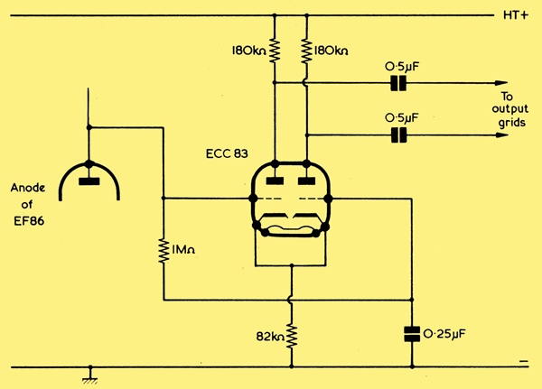
Another version of the Schmitt phase inverter. The two 180kΩ anode load resistors are matched to within 5% and it is recommended that the following 470kΩ grid resistors for the push-pull output valves (not shown here) be similarly matched. (Acknowledgement: Mullard Limited).
An interesting version of this phase-splitter is shown above, this being due to Mullard Limited. The circuit functions in the same basic manner as that of the first circuit, and it should be noted that the grid of the right hand triode has the same bias potential as the grid of the left hand triode by way of the 1MΩ resistor connected between them. The main difference between these two circuits is that the input coupling capacitor is omitted, and the grid of the left hand triode connects directly to the anode of a preceding EF86 voltage amplifier pentode. Although the grids of the two triodes are now considerably positive of chassis, the current which flows in the valves is limited by the cathode and anode resistors. The cathodes take up a potential positive of the two grids which provides a bias corresponding to the current which flows in the cathode resistor, and the circuit is thereby self- biasing. Nevertheless, it is still desirable that the voltage on the grids be such that the bias obtained brings the two triodes on to the centre of their linear working characteristics. In the Mullard application the EF86 is so operated that its anode is about 80 Volts positive of chassis, the HT potential applied to the upper ends of the two triode anode loads being 410 Volts.
As a note on terminology it should be mentioned that the Schmitt phase-inverter is also referred to as the cathode coupled phase-splitter.
|