|
Negative Feedback - Conclusion
In the previous article we considered the difficulties which occur when negative feedback is employed with audio frequency amplifiers. We saw that the most important problem is given if, due to phase shifts in the amplifier, the negative feedback becomes positive feedback. Given sufficient gain in the overall feedback loop the positive feedback can then cause oscillation at any frequency where the phase shift in the amplifier is equal to 180°, and we discussed the essential requirements for preventing such oscillation. In this article we turn our attention to some other factors relating to negative feedback which have not yet been dealt with.
Shunt Voltage Feedback
In the examples of negative feedback we have examined up to the present a fraction of the output signal voltage, n, is applied back in series with the input signal voltage to the amplifier. It is possible, also, for the feedback voltage to be applied back in parallel, or in shunt, with the input voltage. Such a connection is referred to as shunt voltage feedback.
A general instance of shunt voltage feedback is illustrated in (a) below in which, for convenience, we assume that the input signal is provided by an AC. generator. A fraction of the output voltage is fed back in parallel with the input by way of resistor Rf. The plus and minus signs at the amplifier input and output terminals indicate polarity during one half-cycle of the input signal, and are such that the feedback is negative.
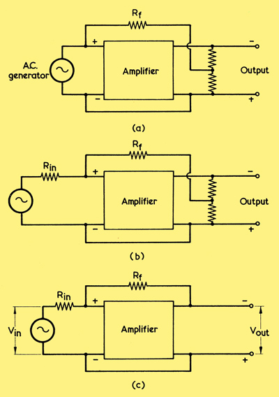
(a) A basic shunt voltage feedback circuit
(b) In practice, the internal resistance of the input signal source has to be taken into account. It is shown here as Rin
(c) A special case of shunt voltage feedback. Under certain conditions, the overall gain is approximately equal to Rf divided by Rin
It is interesting to note that, if the generator in (a) has zero internal resistance, the addition of Rf to the circuit will not change the amplification offered. In practice, the generator (or the circuit it represents) must have an internal resistance. We represent this, in (b), as Rin, and we draw it in series with the generator.
We retain Rf and Rin in (c), in which diagram we now have the whole, instead of a fraction, of the output voltage applied back to the input via Rf. As before, negative shunt feedback is given. We also add the terms Vin to define the signal voltage at the generator terminals, and Vout to define the signal voltage at the output terminals. If, in (c), the voltage gain provided by the amplifier without feedback is high, and if its input impedance is considerably greater than Rf or Rin (as could occur if the amplifier input was the grid circuit of a valve) it can be shown that the overall gain with feedback (ie Vout/Vin is approximately equal to Rf/Rin regardless of the actual gain of the amplifier. This fact is not necessarily of great use for AF amplifier work, but it has applications in amplifiers intended for analogue computer work.
Apart from the fact that the internal impedance of the input signal source has to be taken into account with shunt voltage negative feedback, this method of connection offers the same advantages with respect to distortion and noise reduction, and to frequency response improvement, as does series voltage negative feedback.
Current Feedback
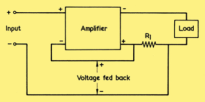
The basic arrangement for current negative feedback. The signal voltage fed back is proportional to the output signal current flowing through R1
A further means of obtaining negative feedback is given by applying back to the input of an amplifier a voltage proportional to output signal current. The general arrangement is shown in the diagram above and it will be seen that the voltage dropped across resistor R1 is applied back in series with the input signal voltage. The fact that we are now thinking in terms of output current infers that the amplifier has an output load, and this load is also shown. For the feedback to be effective the current flow in R1 must be considerably greater than any current which flows at the input terminals of the amplifier. This would occur, for instance, if the amplifier input terminals connected to the grid circuit of a voltage amplifier, whilst resistor R1 was in series with the feed to a loudspeaker.
Current feedback offers the same advantages as does voltage feedback in reducing distortion and noise, and in improving frequency response. As we shall see shortly, it has a different effect on output impedance, and this last factor qualifies its usefulness in AF amplifiers.
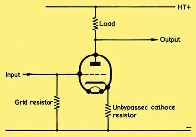
If no bypass capacitor is connected across the cathode bias resistor of an amplifying valve, the resultant degeneration is due to current negative feedback. It is assumed here that the load is an anode resistor
An interesting instance of current feedback is given when a valve operates with no bypass capacitor connected across its cathode, as in the circuit above. The output signal current flowing in the load flows also through the cathode resistor, causing a signal voltage proportional to output current to appear across it. The signal voltage at the cathode has the same polarity as that at the grid (when the grid goes positive, so also does the cathode) with the consequence that the signal voltage between grid and cathode is lower than the input signal voltage between grid and chassis. This is the same as applying a negative feedback voltage proportional to output current in series with the input signal voltage, and the degeneration in the circuit is therefore due to current negative feedback. From Ohms Law, the signal voltage fed back at the cathode is equal to the output signal current multiplied by the value of the cathode resistor.
Input Impedance
The input impedance of an amplifier is altered by the addition of negative feedback. Let us consider first the case of series voltage feedback. It may be helpful, here, to assume for the moment that the impedance presented by the input terminals of the amplifier is due to the resistance of the grid resistor of the first valve, as in (a) below.
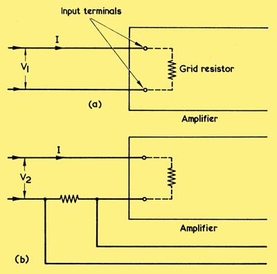
(a) Determining the input impedance of an amplifier without feedback
(b) As is explained in the text, adding series feedback causes the input impedance to increase
When, in diagram (a), a signal input voltage, V1, is applied to the input terminals to cause a current, I, to flow, the impedance at the amplifier terminals is V1/I. In (b) we add series voltage feedback and apply a new signal voltage, V2, to the input terminals. V2 now has to be (l + nA) times V1 to provide the same current flow as in diagram (a).
As was explained in the the first part of negative feedback, input signal voltage with feedback has to be (1+nA) times greater to achieve the same effect (i.e. the same output) as without feedback, where A is the gain of" the amplifier and n is the fraction of the output voltage fed back.
Thus, the input impedance at the input terminals in (b) is:-
V1(1 + nA)/I
The term I is the same in both cases, whereupon it may be seen that the addition of series voltage feedback has caused the input impedance to be increased by (1 + nA) times.
We assumed just now that the input impedance was equal to the resistance of the grid resistor but, in practice, the input capacitance of the valve and stray wiring capacitances have also to be taken into account. The input impedance, therefore, includes reactive components as well. At all frequencies where the amplifier output is 180° out of phase with the input, the input impedance will similarly be increased (1 + nA) times by the addition of series voltage negative feedback.
The input impedance is also increased with current feedback, applied as in the block diagram discussed earlier, where a voltage proportional to output signal current is fed back in series with the input signal voltage.
Applying shunt voltage feedback, as in the first diagrams of this article (a), (b) or (c) causes a reduction in input impedance. This is because an additional current from the signal source flows through feedback resistor Rf.
We have not considered shunt current feedback as yet, but this is quite a feasible method of working and would be given if a voltage proportional to output signal current were applied in shunt with the input signal voltage. As with shunt voltage feedback, shunt current feedback also causes a reduction in input impedance.
Output Impedance
The application of voltage negative feedback to an amplifier (either series or shunt) reduces its effective output impedance.
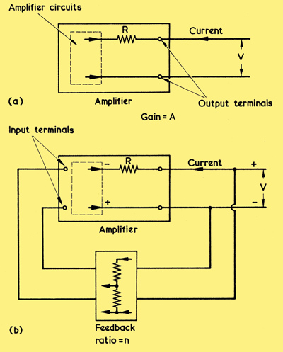
(a) The output impedance of an amplifier may be found by applying an alternating measuring voltage to its output terminals and measuring the current which flows
(b) With voltage feedback the current increases, thereby giving the effect of a reduced output impedance
This may be demonstrated with the aid of the simplified diagram shown above. (a) illustrates an amplifier having a voltage gain A, and it is assumed that its output impedance is given by the physical resistor R, there being zero impedance between the two wires leaving the compartment marked 'Amplifier Circuits' to the left of R.
Now, one way of determining the output impedance consists of applying a measuring alternating voltage to the output terminals and seeing what current flows. The source of input signal is present but offers no actual signal input whilst this process is being carried out. In the first diagram (a) the measuring voltage is V and so the current which flows is V/R.
We need proceed no further with diagram (a) and, instead, we next turn to diagram (b). (b) shows the amplifier of (a) with voltage feedback added. This feedback causes a fraction, n, of the measuring voltage, V, to be fed to the input of the amplifier, whereupon an amplified voltage, nV multiplied by A (the gain of the amplifier), appears at the left hand side of R. Because of the 180° phase reversal in the amplifier,it this voltage has opposite polarity to that of V, and so a greater current flows in R. This greater current is equal to the original V/R plus the new nVA/R and may be expressed as:-
V/R + nVA/R or V(1 + nA)/R.
Thus, the current which flows in R in diagram (b) above is (1 + nA) times greater than in (a). So far as the measuring voltage is concerned, the effective output impedance presented to it by the amplifier in (b) is, therefore, 1 + nA times lower than the impedance presented to it in (a). The new impedance is, indeed R/(1 + nA).
This applies to all amplifiers having voltage feedback. The effective output impedance, with feedback and 'looking back' into the amplifier, is its output impedance without feedback divided by (1 + nA).
With current negative feedback an opposite effect takes place. Without unduly labouring the point this can be demonstrated by turning back to the block diagram.
The basic arrangement for current negative feedback. The signal voltage fed back is proportional to the output signal current flowing through R1
If the load were replaced by a source of measuring alternating voltage, the polarities are such that the amplifier output resulting from the feedback is in phase with the measuring voltage, and the current from the source of measuring voltage decreases. If, for instance, the lower end of the load (now replaced, for argument, by a source of measuring voltage) goes positive, so also, due to the feedback, does the lower output terminal of the amplifier at the left of R1 in this diagram.
In general, it is desirable for the output of a high quality AF amplifier to present a low impedance, as this tends to damp out any fundamental resonance in the loud speaker. In consequence, voltage negative feedback is preferred for amplifiers of this nature. As a final point, the reader should not confuse the output impedance which has just been discussed with the impedances from which the output transformer ratio is calculated. The impedance of an amplifier without feedback and from the loudspeaker transformer primary 'looking back' is always equal to the ra presented by the output valve or valves, and voltage feedback can reduce this value. So far as general design work is considered the output transformer ratio required by an amplifier with feedback is the same as would be required without feedback. The feedback works externally to the valve and its output transformer.
|