|
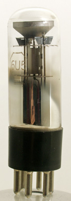
A 6U5 'magic-eye'.
The function of the tuning indicator is to show when the tuning capacitor is in its optimum position for the reception of a signal. Such an indicator is of value in a receiver fitted with AGC because it enables accurate tuning to be achieved even when, due to the AGC action, the volume level from the loudspeaker for a single transmission remains virtually unaltered over a wide range of tuning adjustment.
There are two main types of tuning indicator. One consists basically of a meter, the detection of whose needle indicates the accuracy of tuning. The other employs an electron-ray tube which presents a visible fluorescent display whose area varies according to the control voltage applied to it. The electron ray tube is assembled in an evacuated glass envelope in the same way as is a valve. Both types function by indicating in visual form the voltage across the AGC. diode load or across the signal detector diode load. It will be remembered that this voltage increases as the receiver is brought nearer the correct tuning point for a given signal. If the AGC diode is fed from the anode of the last IF amplifier valve (instead of from the secondary of the last IF transformer following that anode) it is better for the tuning indicator to obtain its control voltage from the signal detector diode load, where the voltage will rise more sharply as the position of correct tuning is approached.
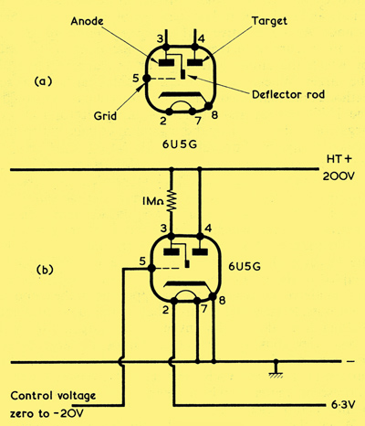
(a) Circuit symbol for the Magic Eye tuning indicator type 6U5G
(b) The 6U5G in a working circuit.
An early version of the 'Magic Eye' is given by the valve type 6U5G and, since this represents what is virtually the simplest type of device available using Magic Eye principles, we shall use it for an introductory example. The 6U5G is fitted on an International Octal (IO) base, and it has approximately the same outside dimensions and shape as any octal-based valve in the G category. Unusually the 6U5G was also supplied with the UX6 base but with the same Type designation. The exhibit on the above link has connections for both variants.
A circuit symbol for the 6U5G is shown above, and it will be seen that this incorporates a triode with its familiar cathode, grid and anode. Connected internally to the anode is an electrode described as a 'deflector rod'. There is also a 'target' (shown in the same way as an anode) which is in juxtaposition with the common cathode but without an intervening grid.
(b) illustrates the Magic Eye in an operating circuit. Here, the target connects direct to the HT positive supply line. The anode connects, via a 1MΩ resistor, to the HT positive supply line also. The cathode connects direct to chassis, whilst the grid connects to a varying control voltage which can range from zero potential to about 20 Volts negative, both with respect to chassis.
The characteristics of the triode section in (b) are such that, for a grid voltage of approximately 20 Volts negative of cathode, the triode is cut off and no anode current flows. Thus, no current passes through the 1MΩ resistor and both the anode and the detector rod are at the same potential as the target. If, next, the negative voltage on the grid is gradually reduced, the triode will commence to pass anode current, causing a voltage to be dropped across the 1MΩ resistor. In consequence, the anode and detector rod go negative of the target by that voltage. As the negative grid voltage continues to reduce the anode current increases, and so also does the voltage by which the anode and detector rod are negative of the target. When, finally, the grid potential is equal to cathode potential, maximum anode current passes through the 1MΩ resistor and the anode and detector rod are negative of the target by the maximum voltage which the device is capable of providing.
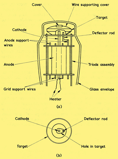
(a) A side view, showing the internal structure of the 6U5G.
(b) Looking down on the target with the cover of (a) removed. The surface shown here is coated with fluorescent material.
We can see how these varying voltages affect the visual Magic Eye display by next examining the diagram above. (a) gives a side view of the 6U5G internal structure and illustrates the triode assembly in the lower section of the tube. The common cathode passes through the triode electrodes, continuing up until it passes through a hole in the lower surface of the target electrode (part of which is shown cut away for purposes of illustration). Also projecting up through the hole in the target is the detector rod, this being mechanically coupled to the triode anode below. A small metal cover affixed above the target hides the upper end of the cathode from outside view and ensures that its red glow does not distract from the display given by the target. (b) gives a view looking down at the top of the target (with the cover which has just been mentioned removed). The surface of the target visible in (b) is covered with a fluorescent material which gives a green glow when bombarded by electrons.
When the tube is operated with the triode section drawing a very low anode current, so that the detector rod is just slightly negative of the target, the target fluoresces over all its surface except for a very small area which is in the shadow of the detector rod.
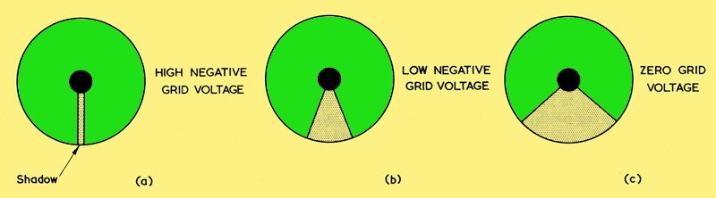
(a) Typical 6U5G display when the triode is near cut-off. All the area within the circle glows green with the exception of the shadow.
(b) The shadow widens as the grid becomes less negative.
(c) The shadow is at its widest when the grid has zero potential with respect to cathode.
(a) above shows the target surface with the tube oriented such that the deflector rod is below the cathode. This fluorescence is due to electrons being emitted radially from the surface of the cathode. If the triode anode current is made to increase by causing its grid to become less negative, the deflector rod potential becomes more negative than that of the target whereupon it offers electrostatic repulsion to the electrons emitted from the cathode. As a result, these electrons do not pass as close to the rod as occurred previously, and the visible effect is that the angle of shadow widens, as in (b). When the triode anode current is at its maximum (as occurs when the grid is at the same potential as its cathode) the detector rod is at its most negative with respect to the target and it offers greatest repulsion. The angle of shadow is then at its widest, as in (c).
Thus, the angle of shadow in the Magic Eye display varies according to the voltage on the triode grid. Working through the effects we have just discussed in reverse order, the angle of shadow is at its widest when the triode grid has the same potential as its cathode. If the grid is made to go negative of the cathode the angle of shadow narrows until, when the triode section is very near cut-off, the angle is at a minimum, as shown in (a).
A minor point not so far mentioned is that, if the triode grid is made more negative again, so that the triode becomes completely cut off, the angle of shadow disappears, and the fluorescent areas on either side give the effect of overlapping each other.
It will be apparent that the Magic Eye can give excellent results as a tuning indicator in a valve AM receiver since the only basic requirement is that its grid be coupled to either the signal diode load or the AGC line. In the absence of signal the Magic Eye will then offer maximum angle of shadow. When a signal is being tuned in, its grid voltage will go negative, whereupon the angle of shadow becomes narrower. The position of correct tuning is indicated by the narrowest angle of shadow in the Magic Eye.
Other Electron-ray Tubes
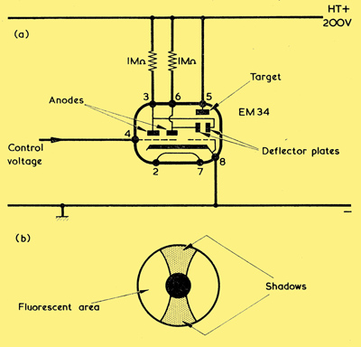
(a) The Mullard EM34 electron-ray tube in a working circuit
(b) The EM34 produces two shadows, one of which closes at a lower negative control voltage than the other.
Later versions of the basic Magic Eye indicator have been produced, and we shall next consider two of these which represent general design techniques. The diagram shows the theoretical symbol for the Mullard EM34, together with the external connections required when it is used in a working circuit. An HT voltage of 200 is assumed. Like the 6U5G, the EM34 has a target, together with a common cathode for both the target and triode amplifier sections. In this case there is also a grid between the cathode and the target. This grid is internally connected to cathode and stabilises emission to the target. In the triode section to the left is a single control grid and two anodes giving, in effect, two triodes having a common grid. Each anode is connected to a separate detector plate assembly which carries out basically the same function as the 'deflector rod' in the 6U5G. There are two external anode resistors, both of 1MΩ. Like the 6U5G, the EM34 is on an octal base, and the target is viewed from the end of the tube.
The internal structure of the tube is such that two shadows on opposite sides of the target are produced as illustrated in (b), one of these shadows closing to its minimum angle for a lower negative control voltage than the other. Under the circuit conditions shown in (a), both shadows are at a maximum angle of nearly 90° for zero triode grid voltage with respect to cathode. One shadow then closes to 5° at a negative grid potential of approximately 4.2 Volts whilst the other closes to 5° at a negative grid potential of approximately 12.5 Volts. The results are that the two shadows offer different sensitivities, and that there is a relatively large degree of shadow angle closure even when the associated receiver is tuned to weak signals.
So far as power supply requirements are concerned, the heater of the EM34 is rated at 6.3 Volts 0.2 Amps. Target current at 200 Volts HT and zero grid voltage is 550 μA, this rising to slightly less than 1 mA for minimum angle of both shadows. The current drawn by the two triode anodes is limited by the series 1MΩ resistors to appreciably less than 400 μA for zero grid voltage.
Other electron-ray tubes employing a target and a triode, whose anode is connected to a detection electrode, have been introduced. A further example is the EM84 which, for an HT voltage of 250, displays a column (viewed through the side of the glass envelope) having a length of approximately 21 mm when the triode grid voltage is zero, this shortening to zero length at a negative grid potential of 22 Volts. With this tube the resistor between target and anode has a value of 470kΩ, and target current varies between 1 mA and 1.8 mA for maximum and minimum column length respectively. The EM84 has a heater voltage of 6.3 Volts at 210 mA, and is on a B9A base. The triode grids of both the EM34 and the EM84 connect into the receiver circuit in the same manner as the grid of the 6U5G.
An interesting electron-ray indicator functioning on somewhat different principles is the Mullard DM70. This is a subminiature device and its glass envelope has a diameter of 10 mm with a length (including seal-off pip) of approximately 44 mm. It has no pins, and connections are made to four lead-out wires which couple to a filament, a 'grid' and an 'anode'.
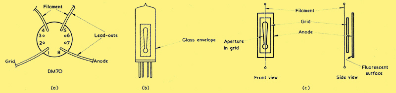
(a) Lead-outs of the DM70. There are no external leads at positions 2, 3, 6 and 7
(b) External appearance of the DM70
(c) The internal electrode structure of the DM70.
The internal structure is illustrated in (c). The anode consists of a metal plate coated with fluorescent material which is viewed through an aperture in the grid, the aperture having a shape rather like an exclamation mark. The grid is a flat electrode, and mounted in front of it is the filament.
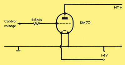
The DM70 connected in a working circuit.
When, as above, the anode is connected to a suitable positive HT voltage, and the grid has zero voltage with respect to one end of the filament, the resultant fluorescent display consists of a column and dot, as shown in (a). Here, the column length is approximately 11 mm. If the grid is then made to go negative, it offers greater opposition to the passage of electrons from the filament to the anode. This opposition prevents the passage of electrons through the narrower part of the aperture, and the result is that the length of the column reduces, as in (b) below.
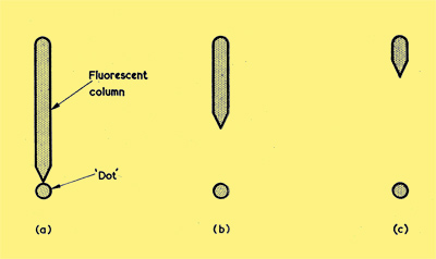
The length of the DM70 fluorescent column decreases as negative grid voltage increases. (Both the column and 'dot' are shown shaded here). In (a) there is zero grid voltage, whilst (b) and (c) illustrate the displays given by increasing negative grid voltage.
If the grid is made to go still more negative the column length reduces again, as in (c). As the grid voltage goes further negative the reduction in column length continues until, finally, both the column and the dot are completely extinguished.
The DM70 was initially intended for use in valve battery portable receivers, and its maximum anode voltage, when the anode is connected direct to the HT positive supply, is 90 Volts. At this voltage, anode current is 170μA for zero grid voltage. The DM70 filament rating is 1.4 Volts at 25 mA. With the 90 Volt HT supply, the column and dot are completely extinguished at a negative grid potential of 10 Volts. The DM70 may also be employed in mains receivers having higher HT potentials, provided that a suitable resistor is inserted in series with the anode. The presence of the resistor causes anode voltage to increase as anode current decreases (due to negative grid voltage) with the result that complete extinction occurs at a greater negative grid voltage.
Thus, with an HT voltage of 250 and a series anode resistance of 1.8MΩ, complete extinction of the column and dot takes place at a negative grid voltage of 34. It is recommended that the grid be connected to the source of control voltage (such as the junction of R1 and C1 in (a)) via a 6.8 MΩ resistor.
The filament of the DM70 may be fed from a 6.3 Volt AC heater supply via a 220 Ω 1 watt resistor having a tolerance of ±5%. In the 250 Volt supply application just mentioned, the filament lead at position 5 should be that which is at chassis potential. For the 90 Volt application, the filament lead at position 4 should be at chassis potential.
Electron-ray indicators have applications other than as tuning indicators. They may be alternatively employed as tape recorder level indicators or as null indicators in test equipment. In the tape recorder usage the control voltage for the electron-ray tube is obtained by rectifying the audio frequency voltage which appears at a suitable point in the tape recorder amplifier, the circuitry being arranged such that the tube gives a readily observable indication (such as complete closure of shadow angle) when the audio level is at the optimum amplitude for correct recording. Test equipment employing an electron-ray indicator may consist, typically, of measuring bridges which are intended to be adjusted for a zero voltage, or null, reading. In both these applications, the main advantage given by the electron-ray indicator is that its triode grid draws virtually zero current from the circuit to which it is connected.
See also Magic Eye display chart.
|