|
Velocity modulation of the electron beam.
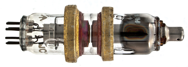
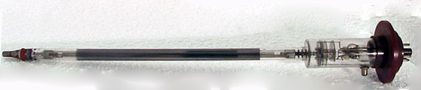
The CV2116 reflex Klystron.
New readers (and old ones who have forgotten) start here. Microwaves, for the present purpose, are chiefly those in what is known officially as the SHF (super-high frequency) band, from 3,000 to 30,000 MHz, wavelengths 10 to 1cm. Among other things they are used for radar and for linking up the BBC television system. A notable example is the Manchester-Edinburgh chain of links on about 4,000 MHz. Valves working according to the usual principles are little or no good for such high frequencies; for one thing, the time that electrons take to cross from one electrode to another is an appreciable part of an SHF cycle, and this leads to various complications; for another, it is difficult to make the distance between the tuning circuits and the working surfaces of the electrodes less than an appreciable fraction of a wave-length. By dint of making the electrodes part of the tuning system and reducing the electrode clearances to paper thickness, exceptional triodes (disc seal type) have been produced capable of oscillating and even amplifying at around 3,000 MHz, but their power and amplification are small. A complete breakaway from ordinary valves is the magnetron, capable of almost incredible performance under pulsed radar conditions - peak output at 3,000 MHz of several thousand Kilowatts, for example. It can also be designed to work at much higher frequencies, but since the whole of the tuned circuit is part of the valve a different size of valve is needed for each frequency band. The magnetron is a diode, with heated cathode and positive anode, but unlike ordinary diodes its electrons flying from cathode to anode are influenced not only by the HT voltage but also at right angles by the force of a powerful magnet, and the energy imparted to them by the HT is not delivered to the tuned circuit after they have arrived at the anode, in the form of grid-controlled anode current, but actually while they are still flying around in the space between the electrodes. Incidentally, it is the interchange of energy between an electrode and electrons moving near it that puts the grid of an ordinary valve more or less out of action at these frequencies. This transit-time effect rules out ordinary valves because it comes in the wrong phase, but magnetrons profit by it because with the help of the magnet it is made to occur in the right phase.
Now that we have, I hope, become used to the idea of tuned circuits that are just little hollows or cavities, and the idea of electrons taking or giving energy to electrodes without actually touching them, it will be easier to tackle the two other main types of microwave valves - klystrons and travelling-wave tubes. After that we can sum up by comparing the merits and limitations of all four types.
I wonder, though, whether there is still some lack of conviction about the influence of flying electrons. Cavity tuning is just a further development of the tendency towards combined and distributed inductance and capacitance exemplified on so many house-tops in the simple dipole, to say nothing of the acoustic analogy presented by sound resonance in rooms - or in a sea-shell held close to the ear. But analogies are not quite so helpful when it comes to visualizing the giving and taking of energy by flying electrons. A falling brick does not impart appreciable energy to anything until it actually hits it. One can study quite considerable books on valves without coming across any hint that the electrons do things to the valve circuits while they are still travelling through space. The reason is that except at microwave frequencies such effects are usually negligible. Of course, it follows directly from basic principles that work is done on a charge that is moving towards an opposite charge under the force of attraction, and vice versa, but this sounds rather highly theoretical and somehow it is difficult to picture action taking place in a circuit due to electrons moving near it. Yet that is what is happening in a capacitor with dielectric material between the plates. It can store more energy when the material is there than when it is not, because the material contains large numbers of electrons on an elastic string, as it were, and when a voltage is applied between the plates they move towards the positive plate, straining at the leash. When the capacitor is discharged they give up this extra energy while they are being pulled back against the attraction of the positive plate.
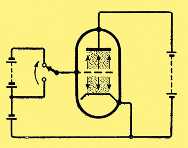
Fig. 1. When the grid of a valve is suddenly made very negative, all electrons in the space are driven away from the grid. While they are doing so, their movements cause grid current to flow, and if this condition is maintained by making the grid potential alternate at thousands of megacycles per second the resulting power loss is heavy.
Or consider what happens at the grid of an ordinary valve (Fig. 1) if a large negative voltage is suddenly applied. All the electrons in the space move away from the grid as fast as they can. Those that had passed through the grid and were on their way to the anode are speeded by a kick in the pants from the repellent negative grid voltage, and those that were on their way towards the grid receive this blow in the face and hurry back on their tracks. The moving of all these negative charges away from the neighbourhood of the grid would upset the potential of the grid unless some negative charges were moved on to it, and these charges flowing in from the negative battery constitute a current, just as if a conductive path had been placed between grid and cathode. An SHF signal applied to the grid alternates so rapidly that the wretched electrons are continuously being pushed and pulled to and fro before they have time to get anywhere, and the compensating current that has to flow in the grid circuit is so large that it inflicts intolerable damping on that circuit. Which is why the grid-controlled kinds of valve wont work. This resistive current must not be confused with the capacitive current that also flows and which could perhaps be neutralized by inductance without serious loss. Whereas no current flows into or out of a capacitance so long as the voltage across it is constant, a constant voltage continues to drive electrons away from the inter-electrode spaces as long as any remain there.
Now suppose that electrons are kept out of the space by absence of anode voltage, combined with slightly negative grid. Switch on the HT voltage, and a mob of electrons will surge forward from the cathode. During the minute fraction of a micro-second during which they are crossing the space to the grid, the grid potential would be upset by the approach of this negative charge if a small positive charge were not brought on to the grid. In practice a positive charge is brought by removing electrons, and the flow of electrons against the EMF of the grid bias source means that energy is flowing into that source. This energy, even if very small, must come from somewhere, and, of course, in this case it is coming from the HT which is responsible for the forcible movement of electrons towards the grid.
Klystrons
The various kinds of klystron are designed to transfer energy to and from circuits by electrons streaming past them rather than into them.
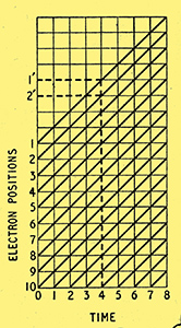
Fig. 2. Diagram showing progress of selected electrons upward at constant velocity, represented by constant slope of the diagonal lines.
Imagine then that a stream or beam of electrons has been produced by a 'gun', just as in a cathode-ray tube, and that it is shooting upwards at a constant speed. In Fig. 2 the numbers 1-10 on the left show the positions of selected electrons in the beam at 'zero' time, which is indicated by 0 on the horizontal scale, marked in very small units of time. The diagonal lines enable the positions of the electrons to be found at other times; for instance, after 4 time units have elapsed electron 1 is at position 1', having moved four spaces upward; electron 2 is at 2, and so on. If the electrons were moving faster, this would be shown by diagonals sloping more steeply, and vice versa. Because they are all moving at the same speed all the lines are at the same slope.
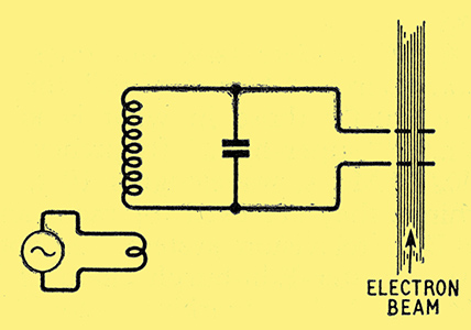
Fig. 3. In the klystron the alternating voltage across a tuned circuit kept in oscillation (here represented by conventional symbols, though actually a cavity resonator is used) is used to vary the velocity of a beam of electrons.
Next, suppose that at the position marked 1 there are two holes or grids through which the beam must pass in quick succession, and that these electrodes are connected to opposite ends of a tuned circuit that is kept in oscillation (Fig. 3). Then during the half-cycles when the upper or second grid is positive there is an electric field between the grids tending to accelerate the electrons, and during the negative half-cycles the electrons are retarded. Let us trace this effect on the position-time diagram for several half-cycles (Fig. 4).
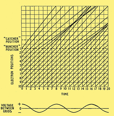
Fig. 4. When the alternating voltage across the tuned circuit (represented by the waveform at the foot of this diagram) is positive, an electron passing under its influence (at the buncher position) is accelerated, as indicated by a steepening of the diagonal line from there on. Negative voltages cause deceleration. The result is bunching, as seen at the catcher position.
Until the electrons reach position 1, where the grids are, everything is as in Fig. 2. The sine-wave drawn at the foot along the time scale shows that at zero time the inter-grid voltage is maximum positive, and the gain in speed of electron No. 1, which is then passing under its influence, is shown as a 25 per cent increase in the slope of its diagonal. The time units are now seen to be eighths of a cycle. So one time unit later the voltage is 1/ √ 2 or 0.707 times peak, and from position 1 onwards the second electron is shown travelling 0.707 x 25 = 17.7 per cent faster than before. When the third electron passes between the grids their difference of potential is zero, so it continues at its original pace. No. 4 is retarded 17.7 per cent; No. 5, 25 per cent; and so on. If we now transfer our attention to a point two spaces above the grid position and watch the electrons fly past we notice - as the diagram clearly shows - that some of them come at longer intervals and others closer together in bunches, like a badly run bus service. Comparing them with the foot of the diagram we see that the periods of sparser electrons synchronize with the negative half-cycles of oscillation, and the bunches with the positive half-cycles. Remember that the electrons shown in the diagram are only selected 'tracer bullets' representing the vastly greater numbers being shot upward. Compared with the average beam current arriving at the grids, the current passing the higher position is alternately negative and positive, in synchronism with the oscillatory grid potentials. So if we were to put here a second pair of grids connected to a circuit tuned to the same frequency, periodically varying beam current would induce in this second circuit an oscillatory current. Since most of the energy of the electrons is due to the anode voltage of the gun, and the energy required from the first tuned circuit to bunch them is relatively small, it turns out that under suitable conditions the oscillatory power developed in the second tuned circuit is greater than that in the first. So the possibility of amplification is opened up. And by back-coupling the second circuit to the first, one can obtain continuous oscillation.
For obvious reasons the first pair of grids is called the buncher. The second is called the catcher, though this name is rather misleading, for it is the energy of the electrons that is caught, rather than the electrons themselves. There is in fact a final electrode called the collector, because that is what it does. The whole point of this scheme being to operate at microwave frequencies, the conventional tuned circuit shown in Fig. 3 is unsuitable. Resonant cavities are used, through which the beam passes.
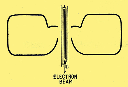
Fig. 5. Section of resonant cavity taking the place of a conventional tuned circuit in the klystron. Oscillatory voltage is developed between the lower and upper holes through which the beam passes.
One form, shown in section in Fig. 5, is shaped like an American doughnut. Another type is actually a short section of coaxial line. The gun consists of a cathode, surrounded except at the outlet by a control electrode at about the same potential, and an anode to bring the electrons out at speed; but except in high-power transmitting klystrons the anode voltage is lower than in television CRT's - sometimes less than 1,000 V. Fig. 4 shows that the catcher might be even more effective if placed farther away from the buncher, but of course the phase difference between the two resonators would be different; and obviously the best position would depend on the initial speed of the electrons, controlled by the anode voltage.
This bunching process is called velocity modulation, to distinguish it from the process by which the control grid in an ordinary valve produces bunching at more or less constant electron velocity. Klystrons have been designed on the principle just described with some success as amplifiers of microwaves, but unfortunately they are rather noisy so cannot be used effectively to amplify very weak signals. The same principle has been adopted in power oscillators developing up to several hundred Watts continuously at around 4,000 MHZ, which considering that something of the order of 1 Watt is enough for the BBC television network links seems to be adequate, to say the least.
For low-power oscillators, used in signal generators, and especially as superhet oscillators in receivers, the choice is nearly always a modified form of klystron in which a single resonator is used as both buncher and catcher. It reminds me of the inexperienced driver who knocked down a traffic-control policeman, and on getting into reverse to apologize knocked him down again. In the klystron the reversing is brought about by a negatively charged electrode called the reflector, placed so as to repel the velocity-modulated beam soon after it emerges from the resonator. When the electrons find a fairly high negative voltage ahead of them they hurriedly reverse and pass once more through the resonator, and if things have been successfully arranged they do so in the correct phase for positive feedback and oscillation. The most convenient method of controlling the phase is by adjusting the reflector voltage.
Tuning Facility
One advantage of the reflection klystron is that there is only one resonator to tune, so there is no possibility of the catcher being out of tune with the buncher. The resonator can be provided with one or more screw plugs for varying the internal volume and hence the tuning, or in some models the tuning is varied over a small frequency band by squeezing the cavity. Even without doing anything to the resonator one can vary the frequency of oscillation up to about 1 per cent - which is, a considerable number of MHz - by varying the reflector voltage, and this is such a convenient method of frequency modulation that FM is usually adopted, for example in television microwave links.
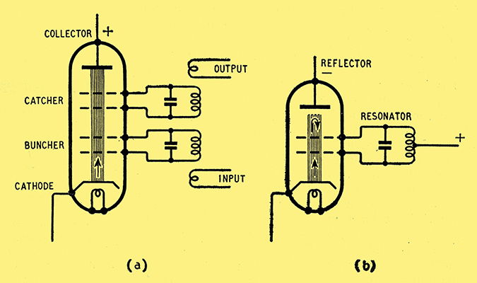
Fig. 6. Diagrammatic comparison of (a) two-resonator and (b) reflection klystrons, the resonators being shown as conventional tuned circuits.
In Fig. 6 the two-resonator and reflection klystrons are compared in simplified diagrams, and Fig. 7 shows the arrangement of electrodes in a typical reflection klystron.
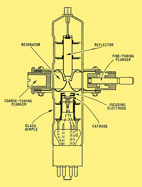
Fig. 7. Section of typical reflection klystron, as used as a local oscillator in a superhet receiver.
Note that the resonator is built into the walls of the valve in the same way as the grid and anode of a disk-seal triode.
It must not be imagined that the subject of klystrons has now been covered, for their behaviour is much more complicated than this simplified story would suggest. But we must press on regardless if we are to get in anything about the travelling-wave tube, which is the most difficult to explain of all. There is already a large book devoted entirely to it, filled with abstruse mathematics. Like the magnetron and klystron, the travelling-wave tube draws on the energy of electrons flying through space at high speed - energy put into them by the steady HT supply. Unlike them, it has no resonator or other tuning device, so its functioning is not restricted to a particular frequency or narrow band of frequencies. It is, in fact, a unique and remarkable device - an aperiodic amplifier of microwaves. In the early days the only aperiodic (i.e., untuned) amplifier was the resistance-coupled kind, and it was effective only for audio frequencies, because of stray capacitance, especially Miller effect. With the development of high gm screened pentodes the frequency band was gradually widened to include RF up to 1 MHz or so, and, with inductance compensation, higher still, to include the whole television VHF band. But the wider the band the lower the amplification that can be obtained per stage. At still higher frequencies the effect of stray capacitance is so devastating that it can only be overcome by merging it into a tuned circuit, and of course that is effective only at and near the frequency to which it is tuned. As one gets beyond the VHF band it becomes increasingly difficult to obtain any amplification at all, even with tuning - hence the strenuous efforts made in disk-seal triodes and klystrons. So the travelling-wave tube, which reintroduces aperiodic amplification in the SHF band, of all frequencies, really is quite an astonishing device. The CV2188, for example, at a fixed adjustment gives 15-19 dB gain at all frequencies between 3,000 and 4,600 MHz simultaneously - a bandwidth of 1,600 MHz!
The reason why the magnetron and klystron cannot do this, you remember, is that the DC power of the electrons is converted into alternating power by careful timing or synchronization effected by tuned circuits, just as in a watch the steady power of the mainspring is converted into regular pulses by the action of its 'tuned circuit', the balance wheel. The magnetron, as at present known, is unsuitable for amplification, so can be left out of the comparison; the klystron, as we have just gathered, needs a tuned circuit to control the timing of the bunches of electrons and thereby apply their energy to the second - or the same - tuned circuit at the right moments to develop oscillations of greater amplitude. The travelling-wave (TWT) tube works on a different principle, for it makes use of the speed of waves, which is practically the same at all frequencies. Instead of the electrons being made to alternate in time they are made to alternate in distance, running alongside the waves and feeding them with energy continuously. This process is difficult to visualize in detail, but I think one can fairly easily get a rough idea of it, once the principle of energy transfer from flying electrons has been accepted.
In a klystron each electron comes under the influence of the bunching voltage only during the fleeting moment when it is actually passing between the fixed buncher grids. This period has to be kept very brief; otherwise the phase of the voltage would have time to change substantially, or even reverse, while the electron was still there. In the TWT it is kept under the influence during most of its journey, for the accelerating or retarding field is made to run along with it, and by so doing to maintain the correct phase all the time. When signals are sent along an ordinary waveguide or transmission line an electric field made in the signal pattern runs along it. But as the speed is not far short of the speed of electro-magnetic waves in space (the speed of light) an enormously high voltage would be needed to make the electrons keep up with it. With reasonable voltages, an electron beam travels at about one-tenth this rate, so the solution is to slow the signal waves down to that. This is very simply done by passing them along a wire wound into a helix (a long single-layer spaced-turn coil) so that the length of the helix is about one-tenth the length of the wire. The signal to be amplified is introduced at one end of the helix, starting a wave moving along it. At the same end of the tube is an electron gun, shooting a beam along the tube inside the helix.

Fig. 8. Diagram representing at (a) the helix of a travelling-wave tube in section, with the electron beam passing through it from left to right. The wave potentials on the helix at the moment selected are shown at (b), and the resulting electric fields inside the helix tend to retard or accelerate the electrons in the beam as shown by the arrows, causing them to bunch (indicated by shading).
Fig. 8(a) shows diagrammatically a length of the helix in section, in which the electron beam and the signal are supposed to be travelling from left to right. For simplicity let us assume that the signal is a sine wave, the voltage along the helix at the instant considered being as shown in Fig. 8(b). The positive and negative peaks are marked along the helix, so at this instant the electric field inside the helix is tending to move the electrons in the directions shown by the arrows. This movement, of course, is superimposed on the high-speed flow from left to right. Since the HT voltage has been adjusted to make this flow more or less keep step with the signal along the helix, the local attractions for the electrons are maintained all the way along, and so the electrons increasingly pile up in some places and thin out in others, as indicated by the shading. In other words, continuous bunching is occurring all along the tube.
Now the original unbunched electron stream was simply DC having no ability to affect the AC signals in the helix. But the bunched stream, which can be regarded as a series of positive and negative charges superimposed on the DC inevitably does induce signals in the helix, of the same wavelength as the bunching signal. While it is true that this original signal must have given up some of its energy to the electrons to make them bunch, this energy is very small compared with the energy of the bunches moving along at high speed. If the HT voltage responsible for their high speed is adjusted so that the phase of the signal induced by them is suitable, it builds up the original signal so that when it emerges from the helix it is stronger than when it went in. Which, of course, is exactly what is wanted.
As one would expect, the voltage needed to obtain maximum amplification is quite critical, and must be obtained from a stabilized supply. For if the speed of the electrons were much different from that of the signal along the helix they would be alternately bunched and debunched as they came into and out of step.
Obviously the electron stream must be kept to a straight and narrow path all the way through the helix, and this is a different matter from focusing in a cathode-ray tube, where it doesnt matter much if the beam spreads out a bit in the middle so long as it is well focused when it arrives at the screen. Besides a first and second anode system to get the electrons off to a good start, a strong magnetic field is provided all the way, as shown in Fig. 9, which is a simplified section of a TWT.
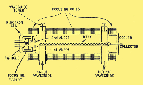
Fig. 9. Simplified section of travelling-wave tube with waveguides and focusing electromagnet in place.
As not very much has been published about these tubes, here are a few details of the CV2188 used in the 250 mile chain of microwave links from Manchester to Kirk OShotts, made by Standard Telephones and Cables, Ltd. This is the first regular service in the world to make use of these tubes. Each repeater station on the route receives signals in the 4,000 MHz band from the previous station, converts them to 60 MHZ IF for amplification, and then converts them back to the 4,000 MHz band (but 37 MHz different from the received frequency) for re-transmission. The output from the frequency changer is not enough, so the duty of the TWT is to raise it from 25 milliwatts to about 1.5 Watts. The second anode and the helix are earthed; the cathode is kept at -3,000 V, the first anode at -1,800 V, and the collector at +50V (to prevent secondary electrons from leaving). Total current is about 14 mA (just over 40 Watts), of which the first anode hardly gets any, and the helix only about 1mA. So most is received by the collector, which is surrounded by a forced-air cooler. The helix, wound 19 turns per inch, has an inside diameter of 0.13in, and the beam diameter is 0.09 in. The average tube life is over 3,000 hours; the senility of a tube can be read off from the supply voltage stabilizer, which is arranged to raise the anode voltage automatically to offset the effects of old age.
For an American type of tube it is claimed that an output of 10 W is obtained in the 6,000 MHz band with 25 dB gain, using 1,200 V. And for a receiving type the gain is 15 dB to 0.5 mW, with a noise factor of 10 dB, using 600 V 0.5 mA. (I can almost hear somebody remarking that travelling-wave tubes are only in their infancy!).
Summing Up
And now for a final summing up of microwave valves.
Disc-seal valves
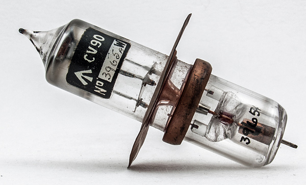
The CV90 can operate at up to 3,000 MHZ.
They persuade ordinary valve principles to work at these unaccustomed frequencies by dint of extraordinary feats of manufacture. They both oscillate and amplify, but performance of even a modest order ceases above about 4,000 MHz, and unless some wonderful new technique is devised there seems to be little scope for substantially increasing either the performance or the frequency. Where it is sufficient to do the job it has the advantages of simplicity and small size.
Magnetrons (resonant-cavity type)
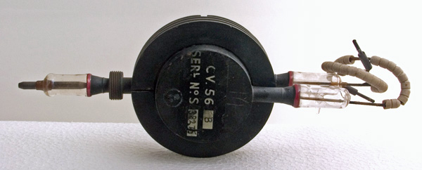
The CV56 S band Magnetron.
Unsuitable for amplification or low-power oscillation or any sort of gradual modulation, but unrivalled for high-power oscillation, especially when pulse-modulated as in radar. Simple and robust, and available for any of the microwave bands, but frequency not easily varied by more than a little, and prone to oscillate at more than one frequency at a time.
Klystrons
The CV35 10cm reflex klystron.
Can be used as oscillators and (if of two-resonator type) as amplifiers, but in latter role are noisy. Particularly suitable as low-power oscillators, especially in superhet receivers, but can be designed for power output rivalling magnetrons in continuous rating and unlike magnetrons they lend themselves very well to frequency modulation.
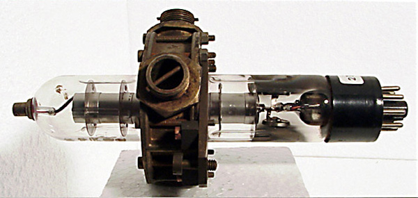
Travelling-wave tubes
The W7/2D commercial version of the CV2188.
Oscillate and amplify, but compare unfavourably with the others for oscillation. Unique in amplifying almost equally over very wide frequency band. Larger and more complicated than disk-seal triode or klystron, but in addition to wide-band characteristics, they beat the triode in performance and the klystron in noise-factor. So we see that while for some purposes there may be room for choice from among these four types, for the most part each has its own job or jobs at which it does best.
|