|
After a lapse of nearly twenty years the common-place cats-whisker crystal detector once again figures as an important item in an otherwise essentially modern radio receiver. As RF amplification is virtually unobtainable on the extremely short wavelength of 3 cm the successful operation of the equipment depends largely on the efficiency and reliability of these new crystal detectors.
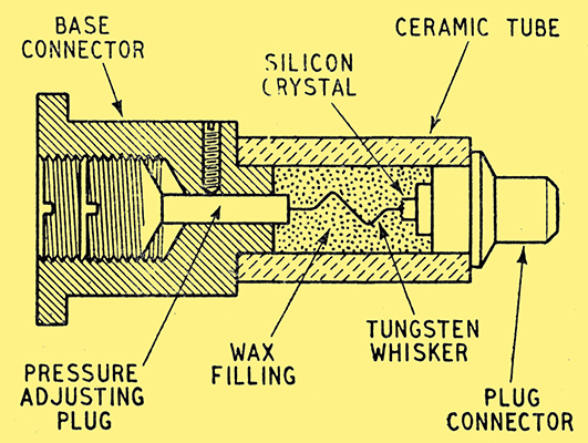
Fig. 1. Construction of the silicon tungsten crystal valve.
Although generally known as a crystal valve, it is basically a silicon-tungsten detector, but externally bears no resemblance whatsoever to its early prototypes. As the sectional drawing in Fig. 1 shows the crystal and tungsten cats-whisker are contained in a small ceramic tube closed at each end by brass plugs and completely filled with wax. This form of construction results in a mechanically robust device in which the contact is quite undisturbed by normal shocks.
When used as a superheterodyne mixer careful control of the local oscillations is needed, and the best guide is a measurement of the rectified current passing through the crystal. This should be between 0.5 and 1 mA for average crystals.
Physically these crystal capsules are quite small, the overall size being just under 1 in long and 0.25 in diameter.
The velocity modulation valve (klystron) is used in the transmitters of certain beacon devices, but its main application in modern radar equipment is as the local oscillator for the mixer stage in the centimetre wavelength superheterodyne receivers.
The valves used for this purpose take the form of either reflection oscillators (reflex klystron) or coaxial line oscillators (Heil Tubes). For the former a single rhumbatron, or cavity resonator, is used, the electron stream being velocity modulated during the first passage through the rhumbatron emerging as bunches of electrons. These are reflected back to the cavity by a negatively biased electrode spaced a critical distance from the back of the aperture.
The coaxial line tubes are generally arranged so that the electron beam passes through apertures cut in the inner and outer tubes, four such apertures being in line. Bunching of the electrons takes place in the passage through the first gap formed by the inner and outer tubes, and the catching effect occurs at the second gap. It is the correctly timed arrival of the bunched electrons at the second gap of the coaxial tube, and after reflection in the reflection klystron, that produces self-oscillation in the valve. Magnetic focusing is generally used in the coaxial line tubes.
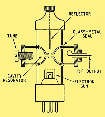
Fig. 2. Details of the latest reflection klystron.
In Fig. 2 is shown, diagrammatically, the basic construction of a reflection klystron, and this is typical of such valves as the CV35, which has a tunable range of about 8.9 to 10.9 cm, and dissipates 10 Watts. Other examples are the CV67 and the CV237.
Typifying the coaxial line valves is the CV234, designed to plug into the end of a coaxial line resonator and so enabling a tuning range of about one octave to be obtained.
The majority of these valves are constructed with a part of the cavity resonator within the glass envelope and a part without, glass to metal seals being used at these points. This enables tuning devices, generally in the form of screwed metal plungers, to be incorporated in the outer portion, together with coupling loops for the RF feeder.
Further variation of the resonant frequency can be achieved by adjustment of the reflector voltage, and within the range of ±15 MHz the variation is approximately 1 MHzper volt change on this electrode.
In the case of valves designed for the 3 cm band the junction areas between the glass and the metal resonator have been found to be a source of considerable RF loss. There are two ways of avoiding this, one is to employ a special harmonic resonator, having the property of producing a potential node at that part of the glass envelope within the resonator, and the other is to totally enclose the resonator with- in the bulb and fit a flexible metal diaphragm at one end for varying the frequency.
Various forms of gas-discharge cells have been evolved to enable radar equipment to be operated with a common transmitting and receiving aerial system. It will suffice here to deal only with the actual device itself.
The TR cells now generally used consist of a cavity resonator tuned to the frequency of the transmitter to which it is connected. Each time the transmitter pulses a high potential is built up in the cell cavity, which causes an internal gap to break down and so short circuits the transmission line at this point.
In one position it is used to protect the delicate crystal detector in the receiver, and consequently the breakdown of the gap must be almost instantaneous, yet restoration of the open circuit condition has to be effected as soon as possible after the pulse terminates. Any appreciable delay keeps the receiver inoperative during that time and the minimum distance from which an echo can be detected is consequently lengthened.
Rapid ionization of the gap within the cell is assisted by including an auxiliary electrode to which a DC voltage is applied. The rate of recovery of the cell on the termination of the pulse is governed by the nature of the gas in it, and so far the best results have been obtained with the cell filled either with water-vapour or a gas mixture containing a high percentage of water-vapour. With a pressure of 6 mm of mercury the recovery time of a typical cell is 2μS.
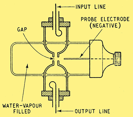
Fig. 3. Water-vapour filled TR spark gap switch.
The basic construction of the TR cell is given in Fig. 3, which represents one of the type in which the cavity resonator is contained partly within and partly without the glass envelope. This form of construction is typical of the CV43.
The chief developments from this basic cell have been mainly modifications for higher transmitter powers and smaller types for insertion in waveguides for use on the 3 cm waveband.
Further modifications were also applied in the design of automatic switches of the ATR type, the main difference being that the priming voltage is omitted since the ionization of the gap need not be quite so rapid as there is no crystal, or other delicate equipment, to protect.
The last few years has produced a better understanding of the behaviour of the common triode valve on the very short waves and although attention has been paid to the reduction of electron transit time, satisfactory operation on the centimetre wavelengths has been achieved mainly by designing the valve as an integral part of the circuit structure. This has led to a radical departure from the hitherto accepted form of construction.
In these new valves the contacts are brought out at points on the glass envelope where they most conveniently fit into the external circuit, which in many cases on the centimetre waves is a coaxial line.
The majority of oscillatory circuits consist of two tunable elements and one valve electrode is common to both. In normal HF and LF practice this is the cathode, but in VHF and centimetre practice it is more convenient to make the common electrode either the grid or the anode. Examples of the common anode style are the VT90 and the CV52.
Further development of the disc-seal form of construction led to the production of the latest type of triodes which have a good performance as oscillators up to frequencies as high as 3 GHz (10 cm). The majority of these are designed for use as common grid oscillators, both for transmission and reception, and included in this class are such valves as the CV90, CV273 and CV288.
CV273 disc-seal triode for insertion in concentric line circuits.
The construction of the CV90, for example, is such that it can be plugged into the end of a concentric line circuit, the anode being connected to the outer conductor. This provides good heat dissipation and as a consequence the valve can be operated with an anode dissipation of 10 Watts and provides about 5 Watts RF output at 50 cm and 0.5 Watt at 10 cm. Early radar transmitters were often modulated by the thyratron class of valve, the main requirement of which is the ability to pass very large peak-currents for a very short duration, usually of the order of 1 μS. In order to obtain high pulse powers an extremely rapid build-up of current through the valve is essential. With the majority of the types so far produced the limit of build-up appears to be about 600 amperes per μS and with a maximum current limit of some 200 amperes.
Certain types of airborne radar equipments, particularly H2S, AI and ASV need high pulse recurrence frequencies to obtain good definition of the image and as the ordinary thyratron is not very satisfactory above about 500 pulses per second a new type of modulator emerged.
Known as the Trigatron, and exemplified by the CV85, it will handle considerable pulse power at the high PRF of 1,200. Actually this device is more in the nature of a triggered spark gap than a thyratron.
Constructionally it consists of two mushroom-shaped electrodes made of molybdenum, between which the main discharge takes place. Protruding through the centre of one is a third electrode made of tungsten, the function of which is to trigger the main gap at the correct instant. Fig. 4 typifies the general form of construction adopted.
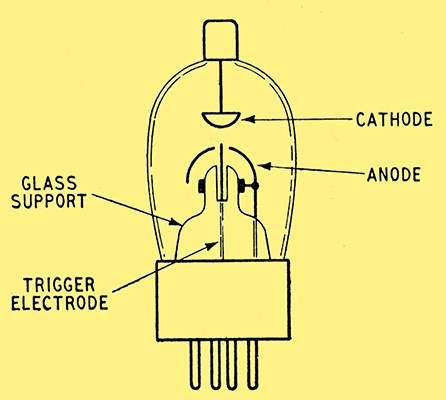
Fig. 4. Constructional details of the Trigatron modulator valve.
The CV85 operates at an anode voltage of 7 kV and will handle 150 kW peak pulse power. Higher powers are delivered by such types as the CV100 and CV125, which give outputs of 250 and 500 kW respectively.
|