|
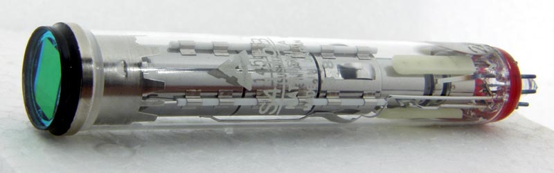
An example of the Newvicon S4145B Camera Tube.
A colour television system drawback that has existed since the earliest experimental systems were devised is that at least three camera pickup tubes are required. This has not restricted colour broadcasting to any great extent because the finances are available to cover the costs. For closed-circuit and small studio use however the cost and bulk of three-tube colour cameras have ensured the continuation of black and white television.
Basic Camera Requirements
In any colour television system there must be at least three camera outputs which provide signals proportional to the amplitude of each of the three primary colours present in the picture and can be combined to give a luminance (black and white) signal. The actual camera output for use with standard equipment need be only the luminance signal plus two colour (or colour-difference) signals since the third colour signal can be obtained by suitably processing the luminance and the other two colour signals.
In a camera using one pickup tube for luminance and two others for the primary colours the light passing through the camera lens must be split so that a black and white picture is focused on to the luminance tube, a red picture on the red tube and a blue picture on the blue tube - assuming that red and blue are the primaries used. Splitting the input in this way is quite a complicated optical process which is carried out by prisms and dichroic filters. The prisms split the light beams, changing their directions, while the dichroic filters extract the colours needed for the primary-colour pickup tubes. In practice to split off the light so that only the red and blue portions of the spectrum pass is wasteful while the low signal level in the tubes would result in poor signal-to-noise ratios. For this reason inverse signals are used - for example yellow which is white minus blue and cyan which is white minus red - for blue and red pickup tubes respectively.
All this is complex and the three tubes must be carefully matched. The scans of each tube must be arranged so that they all cover the same picture area and each tube scan must be linear to the same degree. In addition the grey scales of the tubes must track well and ideally the lag of each tube must balance so that moving objects do not leave coloured trails. These are formidable requirements which have been resolved to an acceptable degree only by expensive means.
Beam Indexing
It would be intolerable if a colour receiver had to rely on optically combining the output from three CRTs - though this has been done for projection TV. The shadow-mask tube, in which separate electron beams are guided so that they strike only the appropriate colour phosphors on the screen, provides a solution. The mind boggles however at the thought of applying a similar arrangement to a vidicon pickup tube. The beam-indexing colour CRT principle is applicable however. The three primary-colour phosphors in such tubes are laid as vertical stripes on the face of the tube. An unmodulated electron beam scanning across the stripes will generate amounts of coloured light output which will result in a grey to white display - assuming phosphors of equal light output efficiency. If the beam is modulated so that it is cut -off while it crosses the green and blue stripes the tube output will be a red display. Thus if the beam modulation and scanning are synchronised any desired colour at any part of the screen can be produced. Synchronisation is achieved by deriving from the beam a reference (index) signal which indicates its position relative to the colour phosphor stripes. This signal can then be used to control the modulation applied to the beam at any instant.
Since beam-indexing colour display tubes first began to look feasible manufacturers have been examining the possibility of a beam-indexing vidicon pickup tube in which coloured layers on the face-plate would result in signal outputs proportional to the strength of each primary colour in sequence. The indexing problems are difficult though easier than those of a receiver display tube because of the better scan linearity of a small pickup tube. There has been something of a clamp-down recently on information suggesting that some success may have been achieved.
RCA Spectraplex Tube
Meanwhile however a colour pickup tube capable of generating a complete colour signal has been developed and is now available commercially: it is the RCA Spectraplex (an RCA trade mark) tube. Imagine a vidicon faceplate divided into stripes alternately clear and two primary colours. As the beam scans over the stripes the amplitude of the electrical signal generated will vary since the amount of light passing through the clear stripes will be greater than the amount passing through either of the sets of colour stripes. The signal amplitude will fluctuate therefore at the rate at which the beam passes from the clear to the coloured stripes. This fluctuation makes it possible to extract a signal from the beam without any indexing system since the fluctuating signal is at a high frequency. If the number of stripes is sufficiently large the signal will be at a high enough frequency to be filtered out from the lower frequency luminance signal. What is more the high-frequency signal will be of an amplitude which depends on the difference between the luminance signal amplitude and the amplitude of one of the primary colours: to put it in a more familiar way, the high-frequency signal will be modulated by a colour signal which represents the difference between the luminance and a primary colour.
Distinguishing the Primaries
We still have the problem however of distinguishing between the two primary colours. A simple modification to the system as outlined so far makes it possible to do just this. If the pitch of one set of colour stripes is different from that of the other, the two sets will produce different carrier frequencies each modulated with its own colour information. In this way a single pickup-tube can generate a luminance and two colour signals which can be easily sorted out in the camera circuitry (and delivered as separate signals or as a composite PAL signal as required.
The Faceplate
The technical difficulties have been very considerable. Because of the way in which the vidicon faceplate is coated with photoconductive material attempts to coat coloured stripes directly on the inside of the faceplate - the most logical place for them - have not to date been very successful. Striping on the outside of the faceplate is easier but the stripes required are so narrow that the passage of light from the outside of the faceplate to the inside is enough to cause some overlapping of the coloured rays.
The Spectraplex vidicon has overcome these difficulties sufficiently to enable it to be manufactured on a production rather than a development basis. Taking the last problem first, the colour filter stripes consist of dichroic stripes on a faceplate which is fibre optic rather than glass of conventional construction. The fibre optic construction ensures that light which has passed through any of the stripes is guided to the corresponding part of the vidicon target with no scattering, thus resolving the difficulty of using external colour filtering.
Colour Stripes
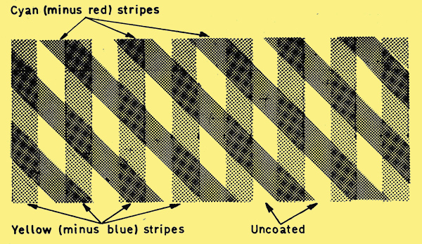
Fig. 1: Stripe pattern used on the faceplate of RCA's Spectra-plex tube. The stripes are laid on the tube's faceplate with a pitch of approximately 48 millionths of an inch. As the beam scans the target a complex signal is generated consisting of a low-frequency luminance component plus two HF carriers which are modulated by the two colour signals.
The colour stripes used are yellow (white minus blue) and cyan (white minus red) and both are laid at a spacing of 530 line pairs per inch of target scan. So that lines of equal spacing generate different carrier frequencies the cyan stripes are 45° to the yellow stripes as shown in Fig. 1. As the beam scans the target, carriers are generated which at NTSC scanning speeds on the 525-line system are 5 MHz for the vertical yellow stripes and 3.5 MHz (5 sin 45°) for the diagonal cyan stripes. These colour stripes are laid with a pitch of some 48 millionths of an inch and it is a good measure of how far we have come in production techniques that such an array can be produced reliably. The Spectraplex is in other respects a fairly conventional vidicon, except that rather higher voltages are used for beam formation as we shall see later.
Camera Circuitry
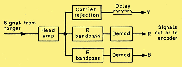
Fig. 2: Block diagram showing the way in which the signal obtained from the target of the Spectraplex tube is processed in order to separate the Y, R and B signals. The Y channel is wideband and the two colour channels narrowband.
The camera circuitry used with the Spectraplex vidicon is conventional as far as the scan and voltage supply portions are concerned. The signal processing portions are rather different of course and are outlined in block diagram form in Fig. 2. The luminance signal is wideband and if full use is to be made of the resolution capabilities of the tube the head amplifier should have a bandwidth extending to 9 MHz (-3dB down). To avoid strong components at the stripe frequencies notch filters at 3.5 MHz and 5 MHz. (in the 525-line system) must be used in the luminance channel. In addition since the luminance amplifier is wideband the Y signal travels faster through it than the narrowband colour signals do through their amplifiers and must therefore be delayed. The luminance amplifier is thus conventional except for the carrier traps and the delay line.
The signal from the head amplifier also passes to the two chrominance channels. Each of these incorporates a bandpass tuned amplifier, working at 3.5 MHz in the case of the red amplifier and at 5MHz in the case of the blue amplifier. Note that since the output of these amplifiers is a signal modulated by the difference between the stripe colour and white the signal obtained from the cyan stripes is red and the signal from the yellow stripes blue. In each channel a detector extracts the colour signal from the modulated signal so that separate red and blue. signals are fed out of the camera or encoded as desired. The bandwidth of the colour amplifiers is ±0.5MHz.
Camera Design Problems
The problems of camera design are mainly concerned with maintaining sweep linearity and focus. If the sweep speed varies the carrier frequencies generated by the colour stripes will also vary and since the tuning of the colour amplifiers is fixed the bandwidth of the colour signals will be altered. It has been calculated that a 1% error in the position of the beam will cause the colour bandwidth to drop to half. The beam focus must be maintained during scanning since the beam must be able to resolve the stripes: any change in beam focus will cause a large change in modulation depth resulting in colour shading. For this reason the voltages at which the tube is operated are unusually high, with about 1 kV on the mesh and around 600 V on the wall anode. Because of losses in the fibre-optic faceplate the tube output is low and a good low-noise pre-amplifier must be used to amplify the 0.3 μA output signal from the target.
Conclusion
The problems have not been solved to the extent that the Spectraplex is likely to drive out the three-tube camera from studio use. Colour shading remains a problem, and there is a cost limit to the use of better scanning coil assemblies. The stripe pattern on the tube causes problems when scenes containing vertical stripes or stripes near 45° are televised since these set up coarse beat patterns with the striping. This can be overcome, at the expense of reduced colour and luminance bandwidth, by slight defocusing: there is also a possibility of reducing the effect optically by a form of low-stop filter. Fortunately there is one bright spot, target lag is not so critical as it is in a three-tube camera.
Another odd effect is caused by the notches in the luminance response where the carrier frequencies have been filtered out: the picture has little resolution at these frequencies so that some objects are almost invisible. This could possibly be overcome by some form of carrier cancellation on alternate lines, but the expense hardly seems worth while.
All in all the Spectraplex is a remarkable achievement which enables colour pictures to be obtained from a camera of size that can be readily hand held. For CCTV work or for small studios it brings colour working down to a price competitive with black and white, thus giving another impetus to the colour bandwaggon. Further development work on single-tube colour cameras, including the development of the beam-indexing tube mentioned earlier, is certainly taking place at this time and developments are expected from Sony and Shibaden as well as from RCA.
|