|
This booklet dates from 1967
- Electrons in Shadow-mask Colour Tubes
- Introduction
- Colour Displays
- From Camera to Viewer
- Building up the Colour Picture
- Three-tube Projection System
- The Shadow-mask Tube
- Three Tubes in One
- Keeping the Colours in Register
- Colour Selection
- Colour Correction
- Construction of the Shadow-mask Tube
- The Glass Envelope
- The Electron Gun Assembly
- Depositing the Screen
- Tube Assembly
- Colour Purity
- Purity and the Deflection Process
- Purity Adjustment Sequence
- Magnetic Shielding and Degaussing
- Convergence
- Effect of Convergence on Purity
- Radial Static Convergence
- Blue Lateral Magnet
- The Need for Dynamic Convergence
- Field Frequency Dynamic Convergence
- Line Frequency Dynamic Convergence
- Grey Scale Tracking
- Black and White Operation
- Modulation of the Beam
- Setting up Sequence
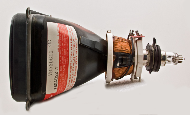
A small modern colour picture tube
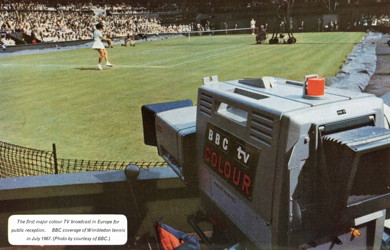
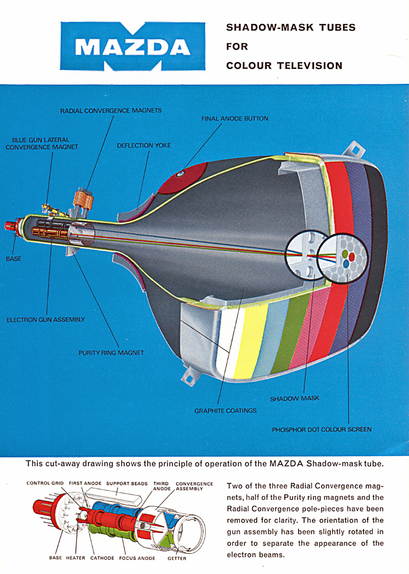
The first public colour television service in Europe was started by the British Broadcasting Corporation in July 1967. At this time, the colour display device most satisfactory for domestic use and capable of quantity production was the Shadow-mask Cathode Ray Tube. MAZDA Shadow-mask tubes were the first to be produced in quantity in Britain, using a new plant designed by MAZDA engineers, which came into operation in 1966.
This booklet describes the construction and operation of the Shadow-mask tube and its associated external neck components. The basic principles of electron guns and beam control are described in the previous booklet in the Electrons series Electrons in Picture Tubes.
The colour television tube is the final link in the complex chain of processes which are involved in carrying the picture from the camera to the viewer and on its ability to present an acceptable picture depends the viewer's judgement of the whole system. It is true that this could be said of the performance of any of the previous links in the chain, but many of these are under the critical supervision of skilled engineering staff whereas the colour tube, employing highly complex technologies, and its associated components, perform their function with only occasional technical attention.
It is interesting to consider the sequence of processes which bring the colour picture to the viewer and we may identify them as follows:
- Derivation by the camera of electrical signals which give a point-by-point description of colour and brightness as the scene is scanned.
- Processing of these picture information signals into a form suitable for transmission in the most economic manner.
- Modulation of the processed signals on to a carrier wave at the transmitter.
- Reception of the transmitted waveform and recovery, in the receiver, of the processed signals.
- Derivation, from the processed signals, of picture information signals of a form suitable for controlling the display device.
- Point-by-point reconstruction of an image of the original scene by the display device in response to the picture information signals.
Many display devices have been proposed and, indeed, developed into a working form. Some have combined optical and mechanical methods, some electronic and mechanical, but for domestic presentation those taking the form of a cathode ray tube are the only ones which have achieved commercial significance and of these, the most important, at the present time, is the Shadow-Mask Tube.
An interesting history of the development of colour television display devices is available in the Proceedings of the Institution of Radio Engineers, October 1951. At that date, a working shadow-mask tube had been developed by the Radio Corporation of America and it had established itself as the most likely tube to go forward to mass production.
Prior to the start of colour television in Britain, we heard arguments on the relative merits of the colour television systems NTSC, PAL and SECAM. It should be realised, however, that differences between the various colour television systems concern only the methods of processing the signals for transmission and, therefore, only apply to stages (ii), (iii), (iv) and (v) enumerated below. The shadow-mask tube, as a display device, is independent of the method of transmission and may be used in conjunction with any of the systems which are in use today.
In general, there are three ways in which a picture, either black and white or coloured, may be presented to a viewer. Firstly, the picture may be produced by inks or paints deposited on a surface. In this case, light (eg sunlight) containing a mixture of many different colours falls on the surface and the various parts absorb or reflect different colours according to the pigments with which they are coated. For example, a green paint absorbs all colours except green which is diffusely reflected.
A second common method involves the projecting of images from one or more projectors on to a white surface which is capable of diffusely reflecting all colours equally well. The colour of any part of the picture is then seen by the viewer to be the same as the colour of the light falling on that part.
Thirdly, the picture itself may be self-luminous with each point of the picture a source of light of an intensity determined by some external stimulus other than a light beam. A picture of this type could be composed of thousands of minute, closely packed, light bulbs each lighted to an intensity appropriate to that part of the scene. A television picture on a directly viewed cathode ray tube is also of this type, since each glowing particle of the screen is a minute light source. The colour of any part of the picture is seen by the viewer as the apparent colour of the light emitted by that area.
In any of these cases, the colour of a particular part of the picture may be obtained either by the use of a single primary colour or by a mixture.
For example, in the first case we may have mixed two different paints to obtain the desired colour. In the second case, a particular part of the picture may be illuminated by the light from two or more projectors while in the third case, a particular area may be composed of very minute, closely spaced light sources emitting different colours. The screen of the so-called black and white television cathode ray tube, if examined with a magnifying glass, will be seen to be composed of a mixture of particles, some glowing with an orange-yellow and some with green-blue light, but when viewed from a distance, the screen appears white. One should note that the rules for colour mixing with lights differ from those when mixing paints such as water colours. For example, a yellow colour is seen when red and green lights are added together.
It is well established that it is possible to match almost any colour, including white, by adding together appropriate proportions of three suitably chosen primary colours and when we are concerned with additive mixing of projected light or of light sources it is found that red, green and blue primaries enable the widest range of colours to be produced.
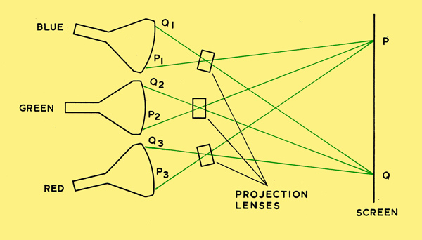
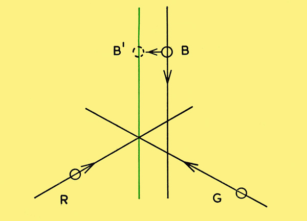
Three-tube projection system.
From the foregoing discussion, it would therefore seem possible to produce a colour picture by the arrangement shown in principle in the above image.
The light from three cathode ray tubes which have, respectively, screens composed of red, green and blue-emitting phosphors is focused by three projection lenses on to a screen. The scanned areas and the optical systems must be adjusted so that the three images coincide as accurately as possible, that is to say, they are in accurate registration each on the others.
A point such as P on the screen will therefore have a colour and brightness determined by the relative brightness's of the points P1, P2 and P3 on the blue, green and red tubes respectively.
To produce an acceptable coloured picture on the screen it will therefore be necessary for the images on the three tubes to be respectively, point-by-point representations of the quantities of blue, green and red required to produce the colours of the corresponding points in the final result. Drive voltages to produce these three images will have to be supplied to the control grids of the three tubes.
Colour pictures have, indeed, been produced by practical versions of this method, but design and engineering problems are considerable and it is difficult to maintain all the possible variables in correct adjustment. Not the least important objection is that such a display would probably be much too bulky for domestic use. However, the requirements of such a display are worth considering, since they indicate the specifications which have to be met by any other display device.
To produce a satisfactory picture, our projection system must meet the following requirements:
- The size, shape and linearity of scanning of three individual component pictures must be the same to a high accuracy.
- The three images must be projected on the screen in accurate registration.
- On each of the cathode ray tubes the light-producing efficiency of the screen must be very uniform over all its area. Failure to meet this condition would make it impossible to display a large area of uniform white, since patchiness on any of the three tube faces would result in deficiency of that colour and hence colour contamination in corresponding areas of the final picture.
- The shapes of the current-versus-grid voltage characteristics of the three tubes must be the same to within close tolerances. If this requirement is not met, it becomes almost impossible to produce a variation in brightness of a mixed colour without also producing a change of hue. This applies particularly to the production of varying shades of grey, which are, in fact, variations in brightness of white and hence involve critically balanced contributions from all three tubes at all levels.
Corresponding versions of these four exacting problems are present in the design and operation of all colour television display devices but, to date, the shadow-mask tube appears to offer the most economic means of achieving satisfactory solutions.
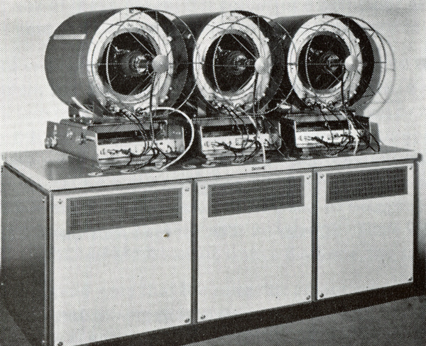
An actual three-tube colour television projector.The Marconi Type V6740 (1967) capable of projecting a colour picture up to a size of 18 x 13.5 feet. (Photo by courtesy of the Marconi Company Ltd, Chelmsford).
Of the four requirements outlined in the previous chapter, the first can only be met by using identical scanning systems on the three tubes. It would therefore seem logical to attempt to design a tube in which the three electron guns are mounted together side by side in a single neck. A single deflector coil fed by only one pair of time bases may then deflect the three beams simultaneously. The cost and difficulties of exactly matching three time bases are then avoided.
At the present time, we shall assume that it is possible to construct a combined phosphor screen in this tube which is so arranged that it emits red light in response to the beam from gun R, and green and blue respectively in response to the beams from guns G and B. How this is achieved will be explained later.
To assist the achievement of exact registration of the separate pictures produced by the three guns, the axes of the three gun assemblies are tilted slightly towards one another so that the three beams meet or Converge at a single point in the centre of the screen when the deflection field is zero. The three beams are then deflected together by the one deflector coil. The path of each beam through the deflector is, in fact, a smooth curve but the overall effect is as if the beam had been deflected abruptly at a point. This point is known as the Apparent Deflection Centre. The arrangement is shown schematically below and the three apparent deflection centres (ADC's) are indicated.
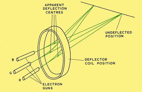
Due to fundamental errors of the deflection process and practical limitations in deflector coil winding, it is almost impossible to keep the three beams converging in a point at the screen as they are deflected horizontally and vertically to scan the picture. An extra deflection unit is therefore mounted behind the main deflector coil and as the main scanning proceeds, this unit introduces small corrections to the deflection of the individual beams to keep them converging accurately.
This unit is usually referred to as the Convergence Unit or the Convergence Yoke. The convergence unit carries sets of coils which develop the magnetic fields needed to provide the convergence corrections. The currents for these coils are derived from the main deflector coil currents by special wave-shaping circuits. Permanent magnets whose effective strength can be varied are also provided to correct for any errors in convergence of the three beams in the un-deflected position. Such errors may arise from slight errors in angular positioning of the three guns. The form of the convergence arrangements and the required current waveforms will be examined in detail in Convergence.
We now have a tube in which three rasters can be individually controlled in intensity by the three guns. Furthermore, these three rasters can be maintained accurately in registration on the screen. It now remains to be seen how a screen can be constructed so that it emits red light when bombarded by the beam from gun R, green when bombarded by gun G, and blue when bombarded by gun B.
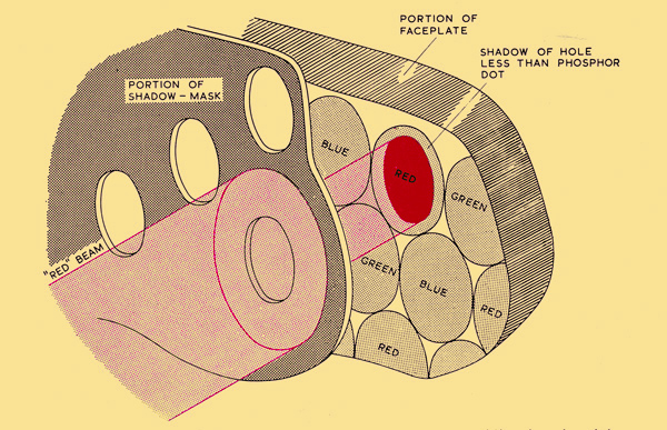
Colour Selection
It will be recalled that after the three beams are deflected by the main deflector coil in order to scan the picture, the paths of the beams are such that all the deflection appears to have taken place at three points called the Apparent Deflection Centres, one for each beam. Thus, from the point of view of an observer at any point on the screen, the beams appear to have originated from these three points.
Suppose then that we interpose a metal plate perforated with many small holes about half an inch behind the glass face of the tube. Furthermore, we arrange that it is at the surface of this plate that the three beams are made to converge as they scan the picture. Electrons in the three beams can only reach the tube face where they pass through the holes. Since, however, the three beams appear to originate from three separate points (the ADC's), they will strike the tube face in different points when passing through any particular hole.
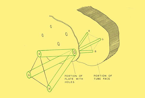
Shadow-mask operation (not to scale).
Corresponding to anyone hole, the points at which the three beams strike the tube face will form a triangle. At the points at which the beam from gun R strikes the tube face after passing through each of the holes, we deposit small patches of red-emitting phosphor. Where the beam from gun G arrives, we deposit patches which are green-emitting and, at the landing points of the beam from gun B, patches which emit blue light are deposited. The centres of these patches, or Phosphor Dots, lie at the points where lines from the three apparent deflection centres, through the centres of the holes in the metal plate, meet the tube face. The metal plate is known as the Shadow-Mask because, when anyone beam is switched on, the unwanted phosphor dots are prevented from being energised because they lie in its shadow. The three phosphor dots corresponding to anyone hole are known as a Triad. In practice, the holes are about 0.012 in. in diameter and they are spaced about 0.029 inch apart in a 25 inch tube in which the total number of holes is approximately 400,000.
Colour Correction
Now the shadow-mask will only perform its function of selecting the colours correctly if the three beams pass accurately through the apparent deflection centres which were assumed when the phosphor dots were deposited on the tube face. Due to small variations in fixing the assembly comprising the three guns into the neck of the tube this may not always be true, in which case unwanted phosphor dots may be energised and the displayed colours will not be pure. To compensate for such errors, a permanent magnet assembly similar to the picture shift rings used on monochrome tubes is placed on the neck behind the convergence unit. This permanent magnet assembly produces, at right angles to the tube neck, a weak magnetic field whose strength and direction can be varied, enabling the three beams to be bent simultaneously until they pass through the correct points. This component is known as the Purity Magnet Assembly.
The achievement of colour purity will be considered in greater detail later. Before doing so, however, it will be helpful to examine some aspects of the construction of the tube and, in particular, the deposition of the phosphor dot screen.
Construction of the Shadow-mask Tube
The Glass Envelope
The glass envelope of the colour tube is very similar in shape to that of the familiar monochrome tube but it is fabricated in a different manner. Like its monochrome counterpart, it comprises a neck, a conical portion and a faceplate. The neck of a 25 inch colour tube has a larger diameter than that of the familiar 110° tube in order to accommodate the three guns side by side. The neck joins smoothly to the conical portion which has a circular cross section at this point but changes gradually to an almost rectangular section where it meets the rim of the faceplate. The face-plate and its rim are moulded as a separate unit into which the screen is deposited and shadow-mask is fixed before it is sealed to the conical portion (see below). In the case of a monochrome tube, the faceplate is sealed to the cone by high temperature gas flames which fuse the two parts together.
This method cannot be used on colour tubes since the high temperatures would result in distortion of the glass and the shadow-mask, so upsetting the accurate alignment of the mask and phosphor dots. Instead, the edges to be joined are coated with a low temperature glass solder or FRIT and then the two parts are placed in contact in an accurately controlled oven. The temperature, although high enough to melt the frit, is not allowed to reach the softening point of the glass bulb and faceplate. Accurate relative positioning of the two parts is maintained during joining by aligning accurately ground reference points or PADS on cone and rim. The image below shows the shadow-mask and the parts of the glass envelope.
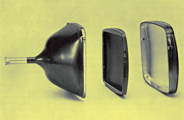
Shadow-mask and bulb components.
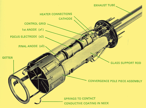
The Electron Gun Assembly
A description of the principles of electron guns of various types is given in the ELECTRONS series booklet Electrons in Picture Tubes. The guns of a colour tube use electrostatic focus. In order to achieve good brightness and small spot size, they are operated at a final anode voltage of about 25,000 Volts. This renders the unipotential or Einzellens unsuitable for use as the main focus lens because such a lens involves the close proximity of cylinders at final anode and cathode potentials. With the small dimensions involved in colour tubes, the voltage stresses would be too high to be accommodated economically using present day techniques. Instead, a lens system using a high voltage focus electrode is used to achieve a more gradual reduction of potential along the length of the gun.
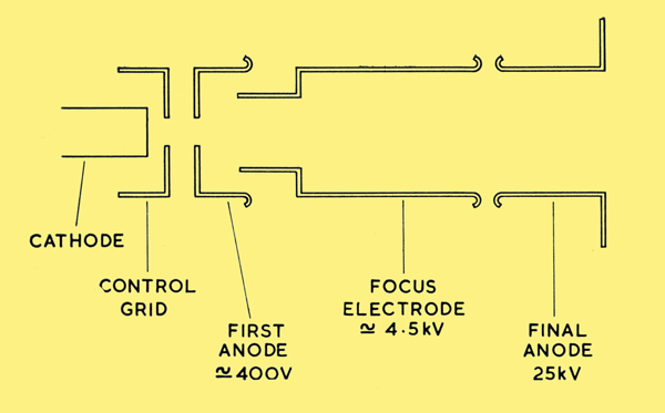
A typical electron gun for a colour tube.
This is shown schematically for one gun above. The voltage of the focus electrode is about 5,000 Volts. There are, therefore, two strong lenses, one between first anode a(1) and the focus cylinder a(2) and the other between focus cylinder and final anode a(3). When the potential of a(2) is varied, the strength of each lens is changed. The focus electrodes of the three guns of the colour tube are connected together so that only one focus adjustment needs to be made. The common lead is fed through one of the base pins which is therefore at a potential of about 5,000 Volts and should be treated with the respect it deserves.
The three guns are assembled rigidly in a common structure with their axes angled so as to meet roughly in the centre of the shadow-mask. The ends of the three final anodes are joined to a common cylindrical structure which contains magnetic pole-pieces which are used in the convergence process. This will be described in the later chapter on Convergence. The final anode assembly carries springs to make contact with the colloidal graphite coating of the inner surface of the cone.
An actual triple gun-assembly.
Depositing the Screen
The shadow-mask has a thickness of only about 0.005 in. and is formed to follow the curvature of the inner surface of the glass face. It is carried on a rigid frame mounted in the faceplate by spring clips so designed that it can easily be removed and replaced accurately in processing. During the deposition of the phosphor dots the shadow-mask acts as a stencil to fix their positions and anyone shadow-mask proceeds through the process with the same faceplate with which it will ultimately be used.
The first phosphor to be deposited, usually the green, is formed into a suspension in a photosensitive lacquer, uniformly coated over the inner surface of the faceplate and dried. The shadow-mask is then placed in position. A small, intense source of ultra-violet light is placed in a position relative to the face-plate which is identical to the position of the Apparent Deflection Centre of the beam from the green gun in the final tube. The photosensitive lacquer is therefore exposed to the ultra-violet light, through the holes of the mask, at the points where the beam from the green gun is able to strike the screen. This exposure hardens the lacquer at those points. The shadow-mask is removed and the screen washed to remove the phosphor except where it was exposed to ultra-violet light. The process is repeated for each of the other two colours, in each case placing the ultra-violet source in the position of the ADC of the appropriate beam.
From this description it might appear that the area of tube face bombarded by the electrons passing through anyone hole would be of exactly the same diameter as a phosphor dot, since both are determined by the shadow of the edge of the hole. If this were the case, there would be no margin for error in the landing of the beam of electrons which passes through the hole. Any inaccuracy would result in a reduction of the illuminated area of phosphor dot. In practice, the size of the phosphor dot can be controlled by controlling the length of time of the exposure to the ultra-violet light and the subsequent processing, as is well known in other photographic processes. By arranging for the phosphor dot to be somewhat larger than the shadow of the edge of the hole, a margin of safety is provided to accommodate small errors in the landing of the electron beam. This is illustrated with only one gun energised.
Relative diameters of beam, shadow-mask and the phosphor dot.
We have previously assumed that the Apparent Deflection Centre is a fixed point irrespective of the angle of deflection of the electron Beam by the deflector coil. This is not strictly true. For large angles of deflection, the ADC moves slightly towards the screen. The movement is only small but if steps were not taken to allow for it in the positioning of the phosphor dots, it would not be possible to maintain purity of colour at the extremes of deflection. Fortunately, it is possible to introduce an optical corrector lens between the ultra-violet light source and the shadow-mask during exposure of the phosphor to compensate for this effect. The combination of light source and corrector lens is known colloquially as the lighthouse. (see below). From the point of view of the tube user, the ADC can be regarded as a fixed point.
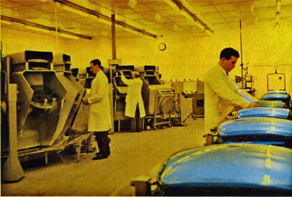
Screening room for MAZDA 25 inch shadow-mask tubes.
When all three sets of phosphor dots have been deposited, the screen is coated with a thin film of aluminium which serves to stabilise potential over the whole screen and also enhances brightness by reflecting forwards light from the phosphor dots which would otherwise have been lost in the bulb. The aluminium is applied by evaporation in a vacuum but the details of the process need not concern us in this description.
Tube Assembly
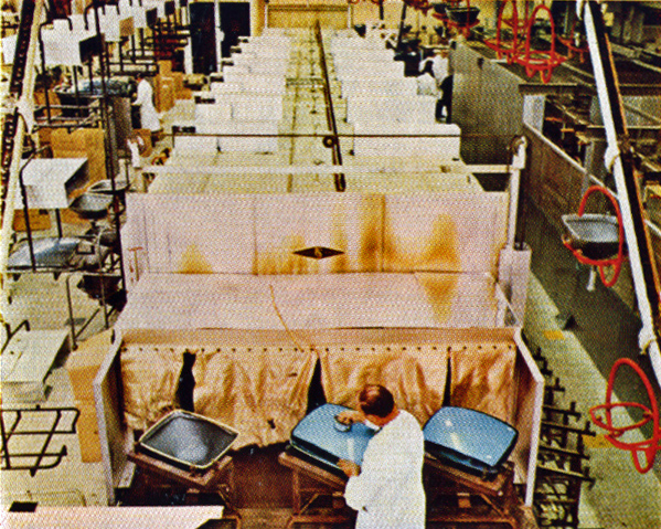
Loading the face sealing lehr.
The screened faceplate with its shadow-mask in position is now sealed to the rest of the bulb as previously described, but first, the gaps between the frame carrying the shadow-mask and adjacent surfaces of the glass are closed with thin metal foil. If this is not done, it is possible for electrons to reach the phosphor dots by scattering and reflection around the edges of the shadow-mask, causing unwanted illumination.
The combined structure of the three guns is then sealed into the tube neck, the orientation being adjusted so that the three guns are directed as nearly as possible along lines passing through the Apparent Deflection Centres. Evacuation, gettering and processing then follow schedules very similar to those employed on black and white tubes.
Colour Purity
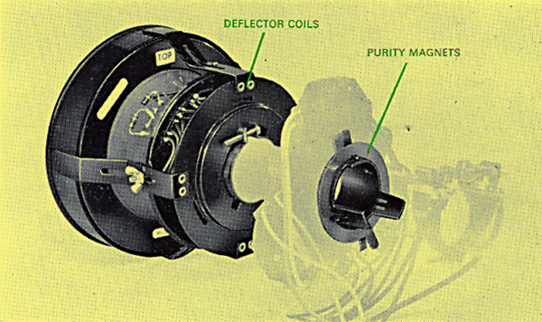
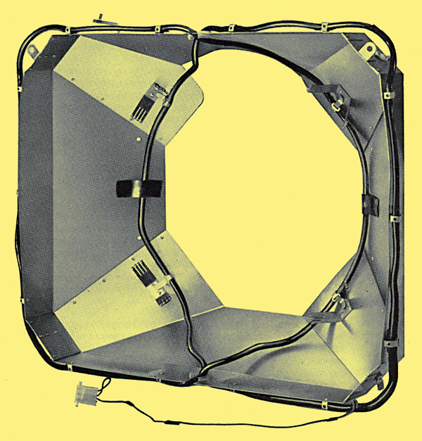
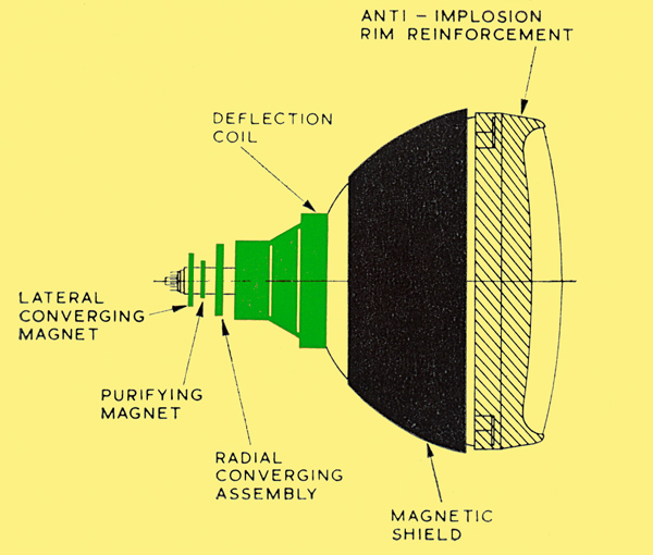
External neck components used for purity correction.
Purity and the Deflection Process
We have determined previously that, in order to ensure colour purity, the Apparent Deflection Centres of the three beams must coincide with the three positions, known as the Colour Centres, assumed when the screen was deposited. Small variations during tube and deflector coil construction may result in failure to meet this requirement. Since the three guns are rigidly fixed to one another by very accurate spacers, it is unlikely that the separation of the beams, when they reach the deflector coil, will be incorrect, but it is quite possible that all three could be displaced together to one side of the correct paths. It is the purpose of the purity magnet assembly to provide a magnetic field which can be adjusted to bend all three beams together so that they once more pass through the colour centres. The three beams then pass through the colour centres when the field in the deflector coil is zero and we should find purity of colour in the centre of the picture.
Nevertheless, when the beams are deflected by the deflector coil we may still find that, away from the centre of the screen, the wrong phosphor dots are energised. This is because the field of the particular deflector coil we are using may be such as to produce Apparent Deflection Centres either in front of or behind the colour centres. By sliding the deflector coil forwards or backwards it should now be possible to bring the ADC's into coincidence with the colour centres, so achieving colour purity all over the screen.
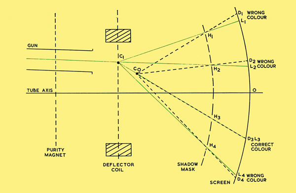
Gun misalignment producing landing errors.
H1-4 are holes in shadow-mask. D1-4 are correct phosphor dots. L1-4 are landing points for electron beam. C0 is the colour centre (manufacture), C1 is the apparent deflection centre (ADC), C2 is the new ADC after adjustment for purity.
This process of adjustment is shown diagramatically above and below where many of the dimensions are exaggerated to emphasise the errors.
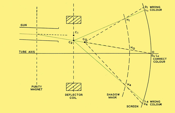
Correct colour at centre using a purity magnet.
H1-4 are holes in shadow-mask. D1-4 are correct phosphor dots. L1-4 are landing points for electron beam. C0 is the colour centre (manufacture), C1 is the apparent deflection centre (ADC), C2 is the new ADC after adjustment for purity.
In the first diagram one gun is shown misaligned so that the un-deflected beam 1 strikes the screen at L2 instead of in the centre, 0. The deflector coil field produces an apparent deflection centre at C1 which is behind and J to one side of the colour centre Co. When the scanned beam passes through the various holes HI, H2, H3, H4 etc., its axis meets the screen at L1, L2, L3, L4 whereas the phosphor dots for this particular colour are deposited with their centres at D1, D2, D3, D4. It will be seen that there is an error in landing of the beam on all dots except D3 which lies in line with the colour centre Co. Therefore, in the area around D3, we should see the intended colour.
In the second diagram the purity magnet has been adjusted to bend the beam before it reaches the deflector coil so that it passes through C0 in its un-deflected state. The deflector coil is still too far to the rear, giving an ADC, in the same plane as before, at C2. In the centre of the screen the landing Lo now coincides with the dot Do and so produces the correct colour, but there are roughly equal errors Dl LI and D4L4 at the extremes of deflection.
By moving the deflector coil forwards, the ADC can be moved from C2 to Co and we shall then have purity all over the screen, as shown below.
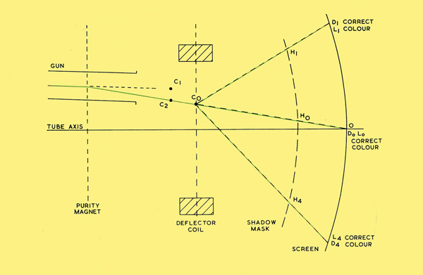
Full screen purity adjustment using deflector coils.
H1-4 are holes in shadow-mask. D1-4 are correct phosphor dots. L1-4 are landing points for electron beam. C0 is the colour centre (manufacture), C1 is the apparent deflection centre (ADC), C2 is the new ADC after adjustment for purity.
In practice, this process is carried out with only the red beam switched on because it is found that errors are most easily seen when using this colour. Having adjusted purity for red, it is usually found that it is also correct for green and blue. The above discussion has assumed that the three beams reach the mask in convergence and this must be reasonably true in order to carry out purity adjustment successfully.
Purity Adjustment Sequence
The adjustment sequence is then:
- Move the deflector coil as far back (i.e. away from the screen) as its adjustments will permit.
- With either a dot pattern or a pattern of vertical and horizontal lines displayed on the tube, adjust convergence to be correct (see Convergence) at tube centre using the Static Convergence permanent magnet adjustments.
- Change to a uniformly energised screen with only the red gun operative. By means of the purity ring-magnets, arrange for the area of pure red to be in the centre of the tube face.
- Slowly slide the deflector coil forwards until the best uniformity of colour over the whole face is obtained.
- Some further readjustments of static convergence may be necessary.
Magnetic Shielding and Degaussing
A magnetic shield with automatic degaussing coil.
It will be appreciated that, since the operation of the shadow-mask tube depends upon the electron beams following precisely predetermined paths, any stray magnetic fields which cause them to depart from these paths will cause contamination of the reproduced colours. A magnetic shield of soft iron or mild steel sheet is therefore usually fitted outside the cone of the tube in the region of the shadow-mask and for some distance towards the deflector coil. This shield, together with the high permeability material of the shadow-mask and the deflector coil yoke usually ensures that operation of the tube will not be seriously affected by variations in the earth's field when the set is moved from place to place.
When, however, the receiver is moved with respect to the earth's field it is possible that the shadow-mask and shield may retain a small permanent magnetisation induced by the earth's field in its first location. This would disturb the electron trajectories and may cause slight colour impurities. It is necessary, therefore, before operation in the new location, completely to demagnetise the shadow-mask and all surrounding metalwork. This is done by subjecting the tube and shield to the field of a coil carrying alternating current at supply frequency and then gradually reducing the alternating field to zero. This process, known as Degaussing, is carried out automatically in most commercial receivers whenever the receiver is switched on.
Convergence
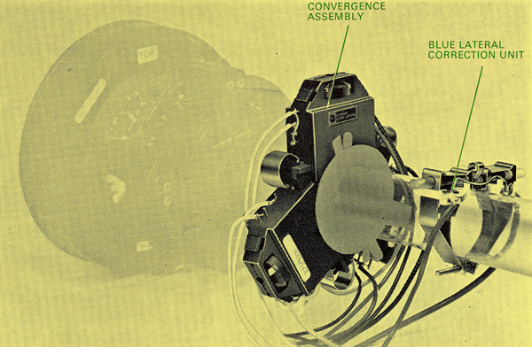
The external neck components for convergence.
Effect of Convergence on Purity
We have already seen that for correct operation of the shadow-mask tube the three electron beams must converge on a single point at all times as they are scanned vertically and horizontally to form a raster. This is required in order to ensure that the three separate rasters are accurately registered, each on the others.
There is a widespread impression that convergence of the three beams at the shadow-mask is essential in order that the mask may correctly perform its function of selection of the colour appropriate to each beam. Fundamentally, this is not the case. Provided the three Apparent Deflection Centres are at the correct points, the correct phosphors will be energised no matter whether the beams are in convergence or not. From a practical point of view, however, if the three beams are seriously out of convergence, it is quite likely that the Apparent Deflection Centre of one or more of them will not be in the correct position and there will be colour impurity on this account.
Radial Static Convergence
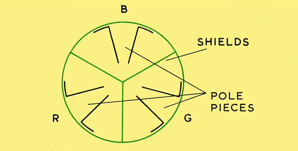
Internal pole-pieces viewed from tube face.
The radial convergence of the three electron beams is controlled by three variable magnetic fields which operate respectively on the three beams individually. The final anodes of the three guns meet in a cylindrical structure which contains three pairs of magnet pole-pieces. One beam passes between each pair of pole-pieces. Outside the neck in the convergence yoke (above) are three magnet assemblies which couple magnetically through the glass with the internal pole-pieces to develop the fields controlling convergence. The image above shows the arrangement of the pole-pieces and the shields between them which prevent interaction of the fields.
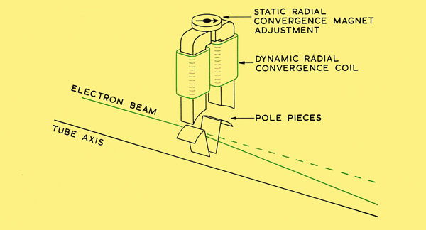
Action of pole-pieces and external magnet for one beam.
Above is shown the form of one of the radial magnet assemblies and the way in which it couples with the internal pole-pieces to control the beam. The external magnet assembly usually consists of two pole-pieces shaped at the inner end to fit closely to the neck and at the outer end shaped so that they almost meet but with a narrow gap between their faces. A disc shaped permanent magnet, magnetised across its diameter, is mounted over this gap so that, if it is rotated, the strength of the field coupled into the internal pole-pieces may be varied. This adjustment is used to bring the three beams into convergence in the centre of the tube face and is usually referred to as Radial Static Convergence.
The external magnet assemblies also carry coils which are fed with currents to correct the variable errors in convergence which take place when the beams are scanned across the tube face. This variable correction is known as Dynamic Convergence Correction.
Blue Lateral Magnet
Movement of R, G & B beams by radial convergence and blue lateral magnets.
It is important to note that no matter where the beams strike the tube face, the movements of the individual spots caused by the convergence correction fields can only take place along three directions spaced from one another by 120°, as shown above, the directions being as viewed from the tube face. Now it may be that due to small errors in assembly, the three lines along which the three spots can be moved do not meet in a single point, in which case true convergence would not be possible using the radial convergence assembly alone. To deal with this error, it is necessary to move one beam sideways to bring the line along which it can move through the meeting point of the other two. The blue beam is chosen to be moved in this manner by means of an extra magnet assembly which moves the blue beam horizontally with respect to the red and green and which is known as the Blue Lateral Correction Magnet. A typical blue lateral magnet assembly, is shown below, which achieves this correction by equal and opposite movement of the blue beam and the red and the green although units are available which move only the blue beam.
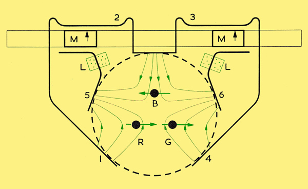
Blue lateral magnet.
The pole-pieces l, 2, 3 and 4, 5 and 6 are strips of soft iron, the magnets M and M are cylindrical rods magnetised across their diameters. By rotating the magnets the field coupled into the pole-pieces is varied, causing the blue beam to move in an opposite direction to the red and green. Coils L are fitted to provide dynamic blue lateral correction if needed.
This magnet is located nearer the tube base than the convergence correction yoke and here a difference between American and European practice must be noted. In Europe, the sequence of components on the tube neck, reading from the deflector coil towards the tube base, is usually convergence yoke, purity assembly, blue lateral correction magnet, whilst in American practice the sequence is more often convergence yoke, blue lateral correction magnet, purity assembly. Different magnet strengths are required according to which order of components is used, and components from a particular manufacturer must only be used in the order originally intended.
The Need for Dynamic Convergence
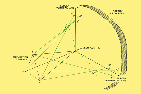
Convergence errors due to horizontal and vertical deflection.
Assume that we have adjusted the radial static convergence magnets and blue lateral convergence magnet so that the three beams converge in a single point in the centre of the tube face; we may now enquire into the nature of the errors in convergence which arise when the three k beams are deflected, together, vertically and horizontally. This, situation is shown diagrammatically above. The three deflection centres are represented by points R, G and B from which the three beams converge to a point 0 in the centre of the screen. When the magnetic fields of the deflector coil cause all three beams to be deflected vertically and horizontally, the points of convergence 0' and on are some distance behind the screen and the three beams strike the screen at three different points forming a triangle. This is not strictly true, since rigorous treatment shows that, on deflection, the three beams no longer pass through a single point, but this additional effect may be ignored at this stage. At the extremes of deflection, therefore, a point on the picture, which should be white, would be split up into three points in the primary colours. Similarly a large area of white would be correctly represented but would have colour fringes along its edges. It is the purpose of dynamic convergence correction to compensate for these errors.
Practical dynamic convergence correction circuits are only designed completely to correct convergence errors along the vertical and horizontal central axes of the picture. It would be possible, if no limit were placed on expenditure, to design circuits to produce complete correction in the corners but these would be far too expensive for general use and the compromise solution, used in practice, usually proves acceptable.
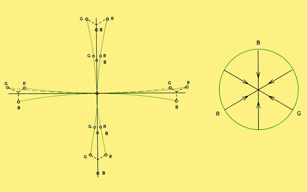
Left: Form of convergence errors viewed from front.
Right: Possible directions of correction by convergence magnets viewed from front.
The diagram shows, in an exaggerated form, the errors in convergence due to vertical and horizontal deflection as viewed on the tube face and the image below serves as a reminder that any corrections by the radial convergence pole-pieces can only be along a particular direction for each beam. The curves on above show the paths followed by each of the spots as deflection proceeds. It will be noted that, except in the case of horizontal deflection of the blue beam, these curves are not symmetrical about the centre of the tube face. This arises from the fact, mentioned briefly above, that if all three beams are deflected through the same angle, without convergence correction, they no longer meet in a single point such as 0' or o'' in the convergence error diagram.
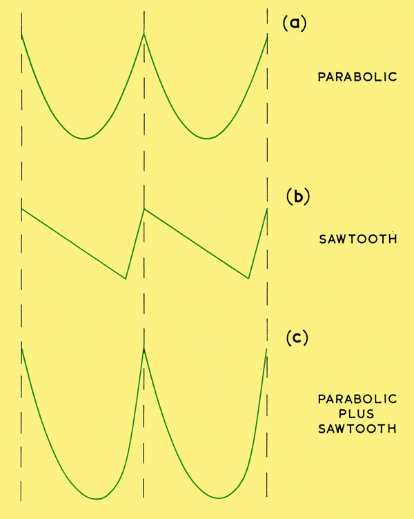
Field frequency correction waveforms.
Field Frequency Dynamic Convergence
We may now consider the shape of the correction waveforms which require to be fed to the windings on the radial convergence correction assembly. It is usual for each electromagnet, such as the one shown before, to have two sets of windings, one carrying vertical or field deflection frequency currents and one carrying horizontal or line frequency currents. Consider, first, the field frequency correction currents required for the blue beam. These will operate in the winding on the pole-pieces coupled with the blue beam which can only be moved vertically. At the centre of the picture no correction is required but at the top and bottom a correction must be applied to move the blue beam slightly upwards. This suggests that a parabolic waveform at field scan frequency is required but closer examination of the forms of convergence diagram above, shows that more correction is needed at the bottom than at the top and this can be produced by adding to the parabolic waveform a sawtooth waveform of lower amplitude (below).
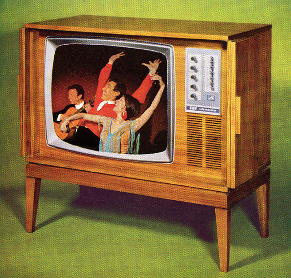
The first fully transistorised colour television receiver in the world. This HMV Colourmaster Model 2700, introduced in 1967, uses a 25 inch MAZDA CTA2550 shadow-mask tube. (Photo by courtesy of British Radio Corporation).
The presence of the CRT was assumed and by transistorised was meant having no valves other than the CRT. The first true all transistor set came with LCD displays in the early 21st century - ed.
Similarly the green and red spots must be moved so that they lie on the centre vertical line and we must remember that they can only be moved in directions making an angle of 1200 with each other. Again we come to the conclusion that the required direction of movement for, say the green spot, is the same at the top of the picture as at the bottom, but since the magnitudes are not equal, the waveform required will be a combination of parabola and sawtooth. In practice the green and red spots are first adjusted to coincide and then the correction waveform for the blue beam is varied to converge it on to the other two.
These waveforms are usually obtained by taking signals from suitable points in the field deflection output circuit and mixing and adjusting the proportions of parabola and sawtooth by variable resistors. For example a parabolic waveform can usually be obtained across the cathode bias by-pass capacitor and a sawtooth from the output transformer.
Line Frequency Dynamic Convergence
The convergence errors due to horizontal deflection at line frequency are corrected by feeding suitably shaped waveforms at line frequency to the other sets of windings on the pole-pieces of the convergence correction assembly. Again, the required waveforms are found to be a combination of parabola and sawtooth except in the case of the blue beam where, theoretically, the curve is symmetrical about the centre of the picture and no sawtooth should therefore be required.
In practice, manufacturing and scanning variations can introduce asymmetry and so provision is usually made for some sawtooth waveform or TILT to be available. The line frequency waveforms may be obtained by taking a line frequency pulse from the line output transformer and integrating it once to provide a sawtooth and then again to provide a parabola. An alternative method is to utilise apart of the line scan sawtooth current itself for the sawtooth component and then, by integration of this, produce a parabola.
It should be emphasised that in this brief description we have considered the basic convergence errors arising from a perfect deflection field and a flat tube-face. A commercial deflector coil will probably have a distribution of magnetic field designed to assist certain features of the purity or convergence processes and in consequence the convergence errors may differ somewhat from the ideal case discussed above.
Grey Scale Tracking
Black and White Operation
The previous chapters have described the means employed to ensure that each gun energises only phosphor of the appropriate colour and also that the three separate pictures so produced are accurately registered one on the other. The other requirement to be met is that the three primary colours must be mixed in the intended proportions at all levels of brightness. This is particularly critical when displaying a black and white picture, when failure to meet this requirement might result, for example, in a good white being displayed at high brightness but the lower levels of grey being tinted with colour. Achievement of this condition is known as Grey Scale Tracking.
Modulation of the Beam
It is beyond the scope of this work to enquire into the nature of the colour television signals but we may say that there are two alternative ways of feeding the picture signals to the tube:
RGB Drive
We may feed red, green and blue signals to the respective cathodes, with appropriate values of DC grid bias fed to the three control grids. This is analagous to the conventional method in monochrome receivers.
Colour Difference Drive
We may feed different proportions of a common black and white signal to the three cathodes and feed the grids with a grid bias plus Colour Difference signals which alter the proportions of current in each gun to give the required colouring. When receiving a black and white picture these colour difference signals are absent. In either case the signal level representing black in the signals fed to the cathodes is accurately maintained at a fixed value with respect to chassis despite changes in signal amplitude. In the simplest method of ensuring acceptable grey scale tracking the DC grid bias fed to all grids is set to a common value which is usually between 100 and 150 Volts negative with respect to the value fixed for black level in the cathode signals. Each gun is provided with a variable voltage supply to the first anode and these voltages are adjusted so that, despite any small differences in manufacture, the beam current of each gun is just cut-off at the pre-set value of grid bias. All guns now have a common cut-off point and it only remains to make adjustments in the relative amplitudes of the signals fed to the three cathodes to obtain a good white at the highest brightness. This method relies on the fact that, apart from small variations due to the state of emission of the cathode, a cathode ray tube gun with a particular value of cut-off has a consistently repeatable curve of beam current versus grid-to-cathode voltage.
Although rigorous analysis indicates that this method is theoretically not capable of giving perfect tracking, results appear satisfactory in practice and alternative methods which are used are much more tedious in adjustment.
Setting up Sequence
External tube components.
- DEGAUSSING
- Switch on the receiver, if automatic degaussing is not fitted then the tube and surroundings must be manually degaussed with a suitable coil.
- FOCUS AND GEOMETRY
- With a suitable pattern of, say, vertical and horizontal bars displayed, adjust focus, raster linearity, amplitude and centring.
- 3. STATIC CONVERGENCE
- Adjust static convergence using the permanent magnets on the radial convergence assembly and lateral convergence unit.
- 4. PURITY
- Switch to a plain field with only red gun operative and adjust for best purity using purity magnets and axial movements of the deflector coil. Re-check static convergence. Check plain green and blue fields for purity and readjust if necessary.
- 5. DYNAMIC CONVERGENCE
- Return to the pattern of vertical and horizontal bars. Readjust static convergence and then adjust dynamic convergence to be correct along vertical and horizontal central axes of the picture. Convergence in the corners should now be acceptable but, if not, it may be possible to obtain a compromise setting which gives improvement. Re-check purity.
- 6. GREY SCALE
- Using a staircase video waveform generator or the grey scale on the centre left of Test Card F, adjust settings of cut-off of the three guns and ratio of video drive voltages so that white and all levels of grey can be reproduced without tinting.
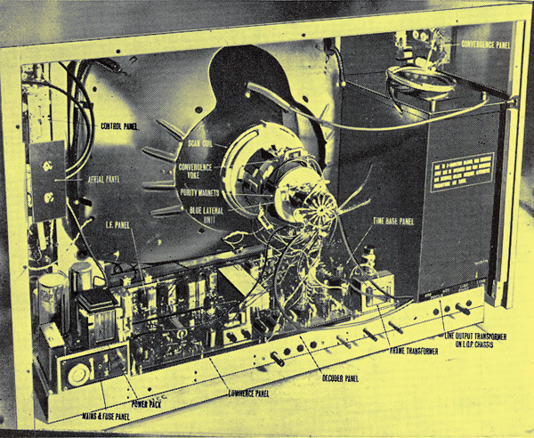
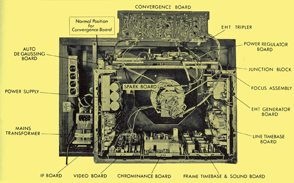
Inside a typical hybrid receiver of 1967, the Decca model CTV25. (Photo by courtesy of Decca Radio and Television).
A MAZDA CTA2550 fitted in a 1967 solid state Ultra Bermuda 6700 receiver using modular printed circuit construction. (Photo by courtesy of BRC).
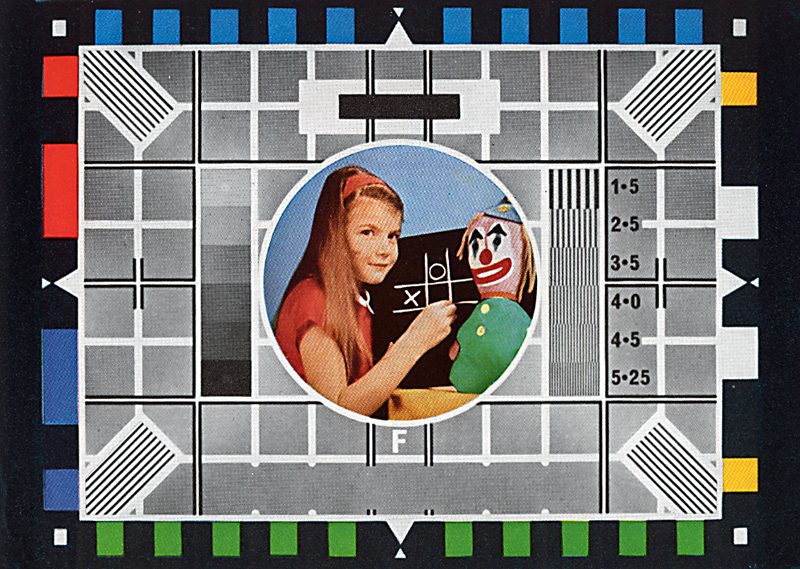
Colour test card F as it is transmitted. A properly set-up receiver will mask of parts of the coloured castellations.
|