|
This amplifier advertised on ebay caught the author's eye as there was no mains transformer and so probably it had a switch mode power supply and DC heaters. The format matches the 6P3P mini amplifier.
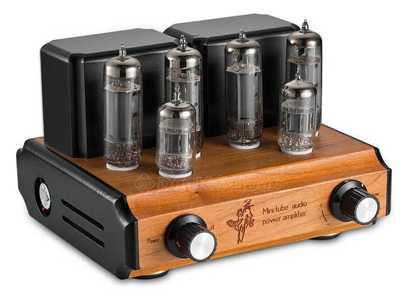
The amplifier as advertised on ebay.
The amplifier was well packed. Inside the outer cardboard box was an expanded polystyrene box. Inside the inner box the space was filled with packing pieces so that nothing could move. The valves were wrapped in bubble wrap and the chassis was also carefully wrapped.
The amplifier as supplied has no instructions or any other documentation. The ebay advert does give adequate information.
The top surface is real wood. On the right side plate is a small fan. The advert claims an output of eight Watts per channel but does not give a distortion value for this level.
All but one of the valves was unmarked. One 6P14 being the exception. The double triodes remain a mystery but the design suggests ECC83 equivalents.
Out of the box the amplifier has a two pin mains plug and adapters for various countries. This was changed for a UK standard plug and the amplifier connected to the author's Mission bookshelf speakers. On switch on the fan starts and if sitting next to the amplifier the fan can be heard. There is no hum - DC heaters! But the cooling fan can be heard across the room. The fan is only noticeable when there is no signal.
Subjectively the amplifier produces an excellent room filling sound. Time to put it on the bench and measure the performance. The test set-up is described here.
The test set-up was in place following the re-measure of the 6P3P mini amplifier. All the connections transferred easily as the back plate format is the same for both amplifiers.
A low amplitude 1 kHz sine wave signal was applied to both channels and the amplitude increased until the bottom of the trace started to flatten. Switching to the spectrum analyser revealed a small second harmonic peak. As the input amplitude was increased a third harmonic peak appeared. Thus the original input was at the correct value.
The output voltage across the 8 Ω load was much lower than expected. Both channels had the same RMS value. Removing the drive from one channel and retesting the signal produced the same result as the first test.
This amplifier is advertised at 8 Watts per channel. The objective measurement did not support this for distortion-less output. 1.3 Watts was recorded, equivalent to 1.43 Watts per channel when corrected for sine wave drive to a cathode biased amplifier.
The measured output power (in mW) into 8 Ω. Black = Left, Orange = right.
Thinking that this cannot be the correct answer, the author increased the input to obtain a maximum RMS voltage into the load resistors. At a maximum of five Volts the sine wave had been distorted into a square wave. Just over three Watts from a pair of EL84 equivalents. A single ended EL84 easily produces three Watts.
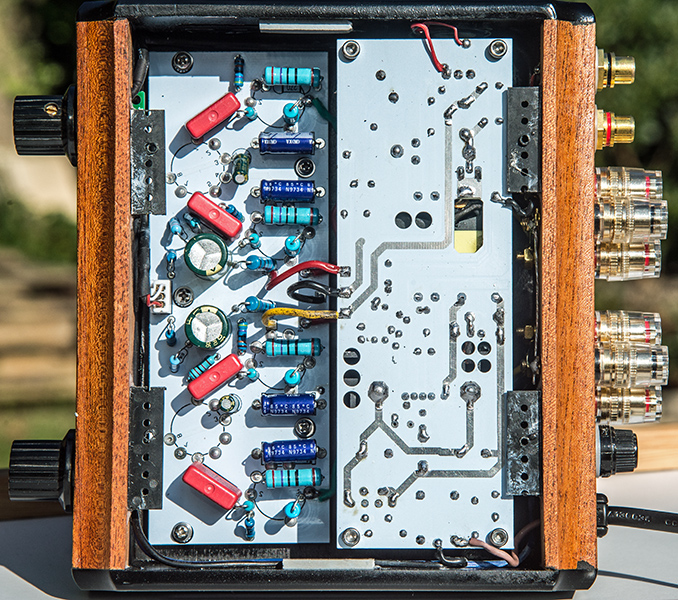
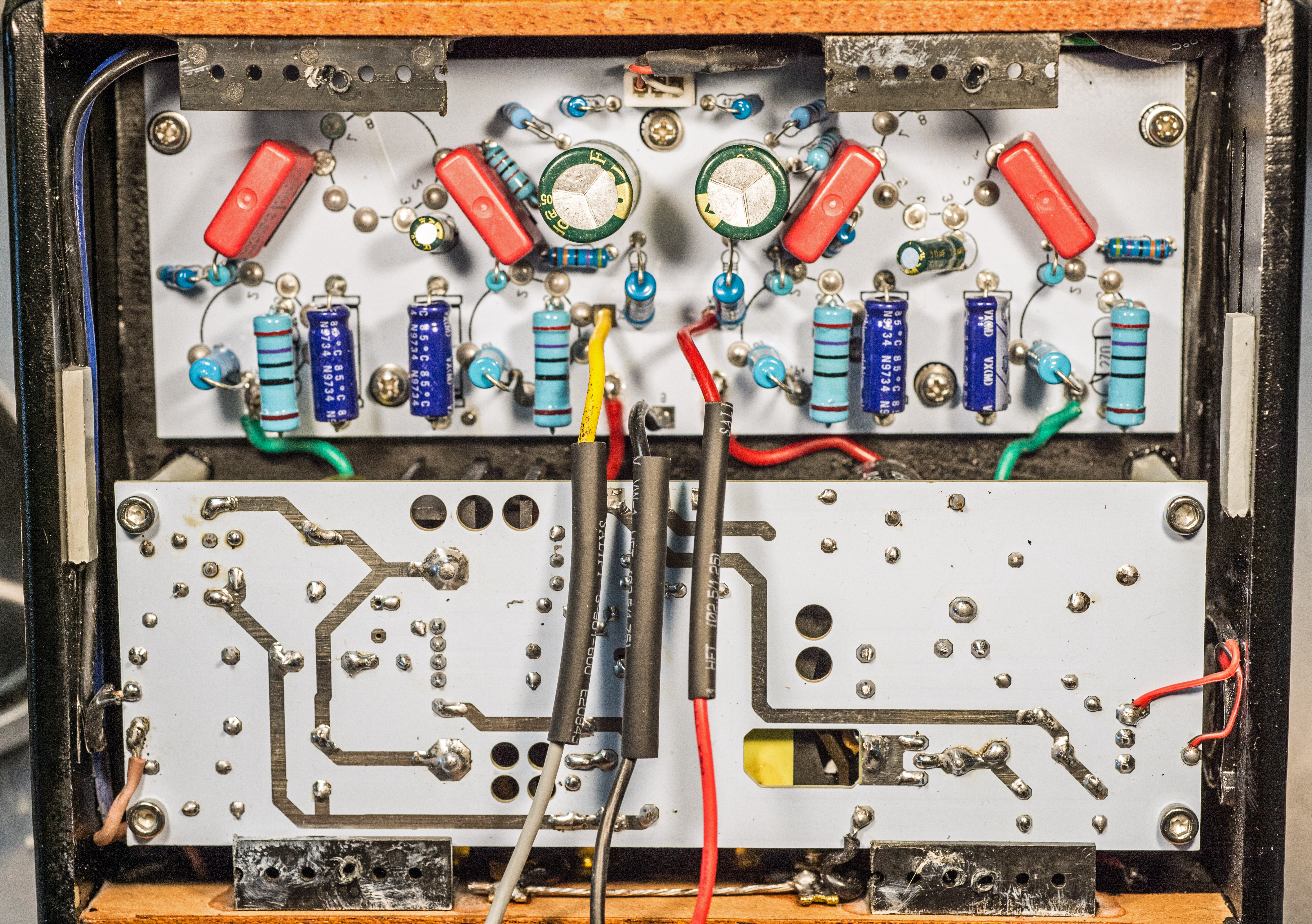
The amplifier board and power supply.
With the lower cover removed it was clear that the power supply was switched mode as expected. The power supply connects to the amplifier board with three wires, ground, HT and heater. The output valves screen grids are fed from the HT line by a resistor. The output transformers are connected to the amplifier board for HT and anode. There is no negative feedback connection visible. The 6P14's have individual 270 Ω cathode resistors bypassed by an electrolytic capacitor.
The components are of good quality and the boards are well made. The coupling capacitors are WIMA.
Allowing the amplifier to warm-up the various voltages were measured. The heater rail is 13 Volts, this indicates that the output valves are connected in series. Also with a 13 Volt DC rail available the power supply fan runs at full speed. In the 6P3P mini amplifier the heaters are run from 6.3 Volts and the fan is quieter. The HT rail was measured as 263 Volts. The voltage on one 6P14 cathode was 7.6 Volts indicating a cathode current of 28 mA.
The next step was valve substitution. A stock of tested Brimar and Mullard valves was used for the substitution in one channel. A Tungsram EL84 and a Brimar EL84 were fitted first. Testing with a 1 kHz sine wave produced identical results from both channels - still low. The unknown double triode was replaced with a known good Mullard ECC83. The results from both channels were identical. Thus the unmarked double triodes are ECC83 equivalents.
The final substitutions were ECC81 and ECC82. In both cases the input voltage had to be increased, more for the ECC82 as expected. The power output was little changed.
The supplier was then contacted for their comments.
The obvious next step is to power the amplifier board from an external power supply.
Initial Conclusion
If the author had just unpacked the amplifier and connected it to a signal source and quality speakers he would have been delighted with the performance. It is an attractive product and looks fine in a domestic setting. The sound is clear and has ample punch. Subjectively a great amplifier. However, on test it clearly does not comply with the advertised claims. Five Watts per channel of undistorted output would make this amplifier an excellent buy, 1.5 Watts is just wrong.
Next Steps
The author contacted the supplier and sent all of the measurements and performance diagrams. The comment was made that at the limited power the sound was fine. The first response was to ask what amplifier was being enquired about. Details sent and the response was that the issue was being referred to the factory. Long pause, finally an email arrived saying "the skill director also don't understand what does you mean, if the item can works well?'. Not impressed! Time to open the box and investigate.
Working with a live mains input switch mode power supply is too risky in the author's opinion. The three power supply connections to the amplifier were un-soldered and leads added so the unit could be powered externally.
The current drain at 75 mA per channel was too much for the Heathkit bench HT supply and one channel had the valves removed. Powering with 315 Volts moved the output power up a small amount but nothing significant. At around 1.5 Watts the lower portion of the sine wave started to flatten. This should indicate that the bias was too low, but the 270 Ω cathode resistor is what Mullard specify. Nothing, including swapping all the valves individually brought about an improvement. Time to sleep on it and ponder.
The problem started to be resolved when the original underside image was looked at again. Only two wires run from the board to the output transformer. A closer look was indicated.
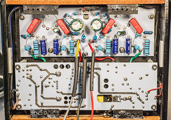
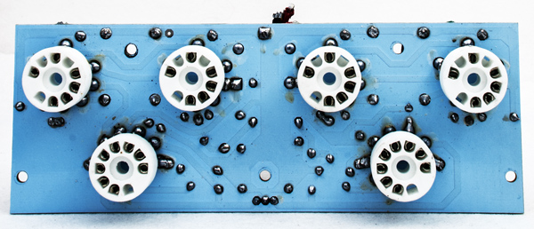
The underside of the board - a closer look.
Clearly only two wires to the primary of the output transformer. Time to look closely at the valve-holders.
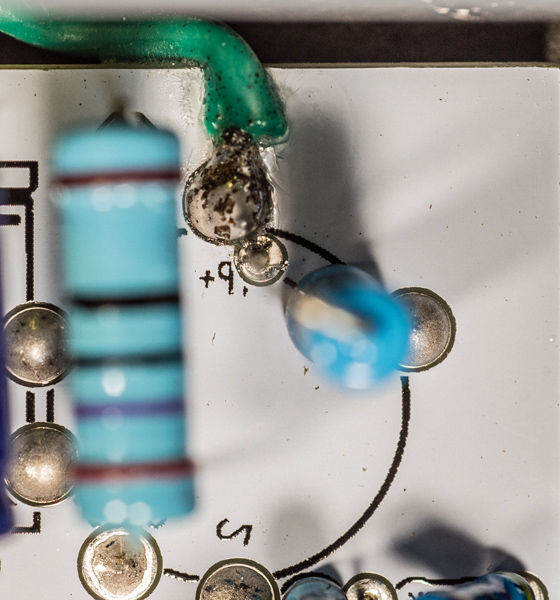
The outer 6P14 - wire attached to the anode pin and the screen grid fed from the anode contact via a resistor.
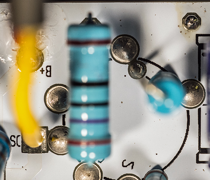
The inner 6P14 - the screen grid fed from the anode contact via a resistor but no external connection to the output transformer.
The next step was to power the amplifier with just one output valve. A 10 Ω resistor was plugged into pins 3 and 4 of the other valve-holder to simulate the presence of the valve - the heaters being wired in series.
Powering the amplifier produced a clean sine wave of 3.1 Volts across the 8 Ω dummy load.
Checking the output of the double triode produced two identical waveforms as below.

The 6P14 input waveforms - no phase inversion.
The two anodes are connected in parallel - not push pull.
The cathode resistors at 270 Ω each are appropriate for the Mullard 5-10 push pull pentode configuration. In single end mode the cathode resistors in the Mullard 3-3 amplifier are 560 Ω. This explains why the output trace with the lower point flattening indicated too low a bias point.
Conclusion?
This amplifier is just wrong. The DC input is around 15 Watts per channel for 2 x 1.5 Watts output an appalling conversion rate.
The amplifier is advertised as push pull - it is not. Neither is it correctly a parallel single ended amplifier. With 270 Ω cathode bias resistors one is forced to conclude that this is neither one nor the other. The question remains - why?
The Saga Continues
It was agreed that the amplifier would be returned - it was. The supplier then offered a refund or a replacement. Assurance was given that they had the push-pull version to send. Time to wait for the replacement.
The replacement arrived with a different, and very attractive wooden chassis. The amplifier was connected to the Jamo system and subjectively tested. The sound was room filling and even 37 Hz bass was reproduced. This looked to be a competent product - time to look inside.
Inside the amplifier was exactly the same as the first parallel pair amplifier. Email to supplier. The reply was to ask for more photographs and the following images formed the reply.
The main board. It is double sided and well made.
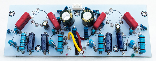
The component side. The board needed to be removed from the case in order to trace the circuit.
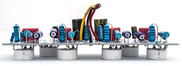
A compact design.
Having removed the board and traced the circuit roughly it seemed sensible to draw the circuit diagram neatly for this article.
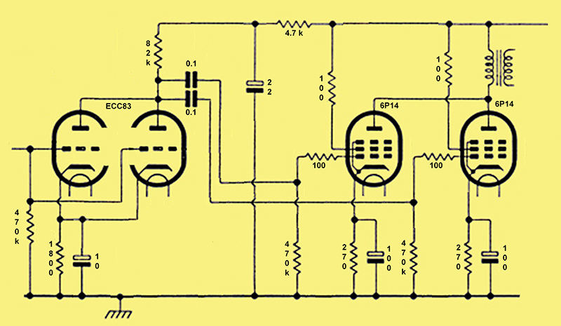
Circuit diagram.
The output transformer has a turns ratio of 20.6 giving a primary impedance of 3,250 Ω
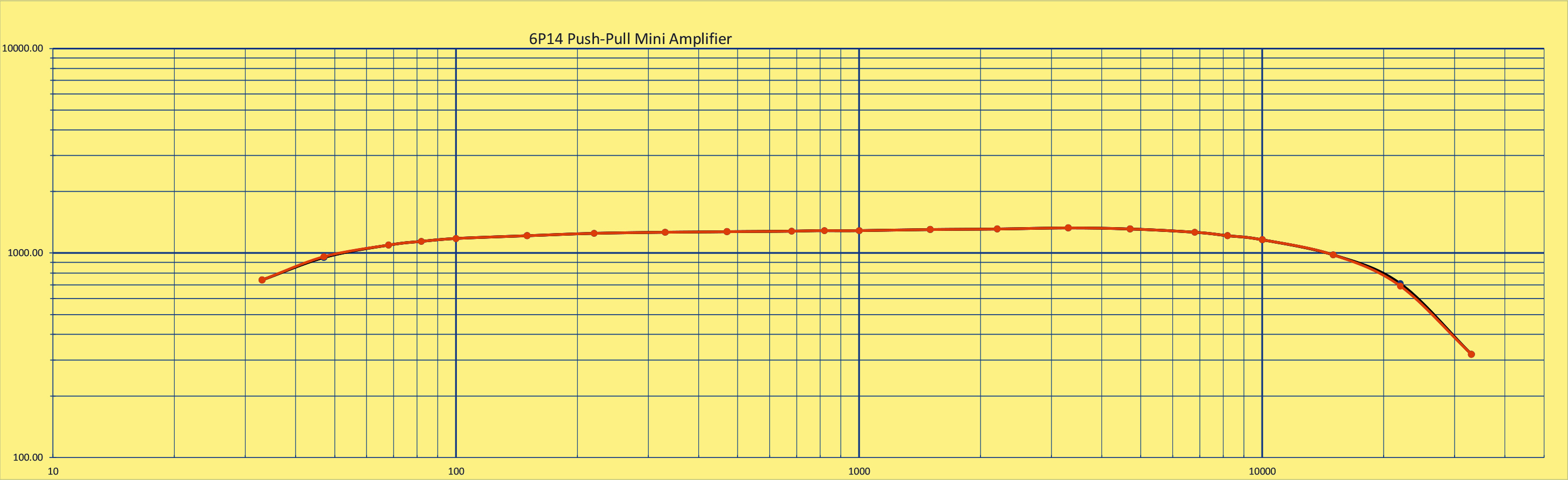
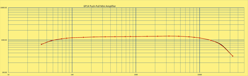
The replacement amplifier was response tested and this second example also produced 1.5 Watts per channel when sine wave tested.
A response from the supplier by return apologised and said that factory must have sent the wrong batch. Refund to follow. Case closed.
|