|
This amplifier advertised on ebay caught the author's eye as there was no mains transformer and so probably it had a switch mode power supply and DC heaters. The design is mirrored in the 6P14 mini amplifier.
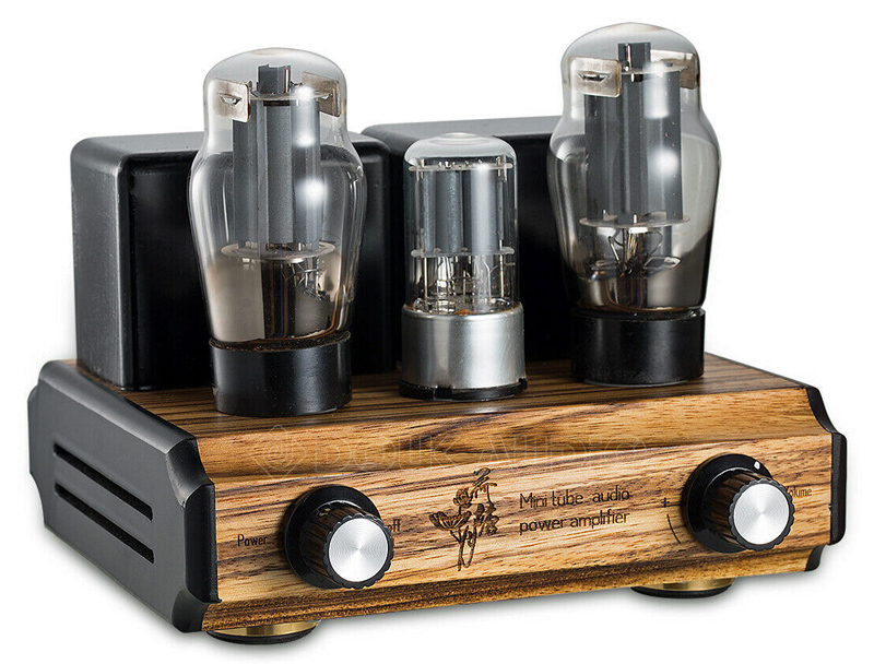
The amplifier as advertised on ebay.
The 6P3P is a Chinese version of the classic 6L6G and the 6N9P double triode is a version of the 6SL7GT. No circuit diagram is supplied with this complete amplifier but with just one double triode, the circuit will be a single triode voltage amplifier feeding the output valve. There will not be sufficient gain for the application of negative feedback.
The amplifier weighs 2.5 kg and the top surface is real wood. On the right side plate is a small fan. The advert claims an output of five Watts per channel but does not give a distortion value for this level.
Out of the box the amplifier has a two pin mains plug and adapters for various countries. This was changed for a UK standard plug and the amplifier connected to the author's Danish Jamo speaker system. On switch on the fan starts and if sitting next to the amplifier the fan can be heard. There is no hum - DC heaters! The author's EL91 amplifier uses DC heaters and the absence of any hum is most welcome. From a metre away the fan is quiet. It is a 12 Volt fan that is run from the 6.3 Volt heater supply. The Chinese FU-32 amplifier has AC heaters and hum is noticeable between tracks. This also is the case with the EL34-B amplifier.
Subjectively the amplifier produces an excellent room filling sound. Visually the EL34-B amplifier is the more impressive but is also much more expensive.
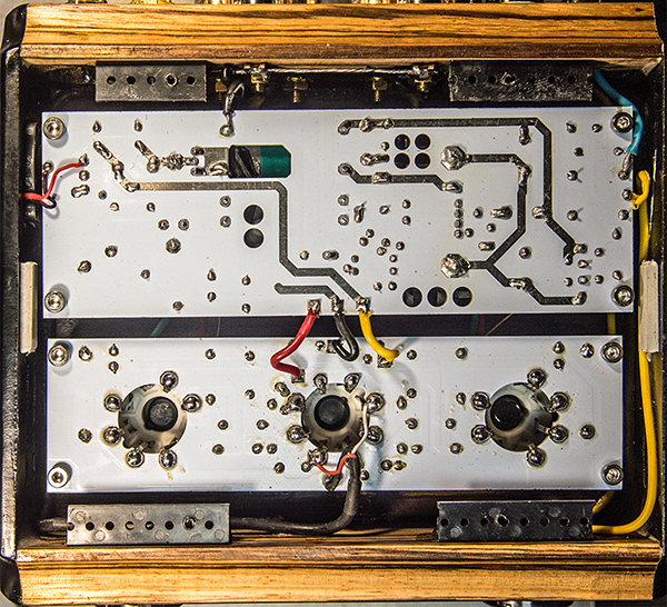
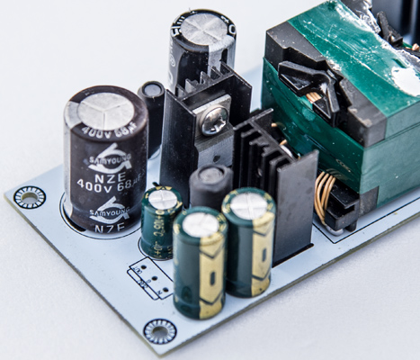
With the bottom plate removed.
At the workshop the base plate was removed. The switch mode power supply provides just three connections to the amplifier board. A ground connection a heater supply of 6.78 Volts DC for the heaters and an HT rail of 271 Volts. The heaters are thus run 7% over their nominal rating. There is no visible voltage adjustment on the power supply board. A slim 0.22 Ω ceramic resistor was inserted in place of the yellow wire between the power supply board and the amplifier. The heaters were then driven by exactly 6.3 Volts.
The cathode resistor reads as 256 Ω and when running the cathode is at 16.45 Volts. This equates to a cathode current of 64 mA. The input power is thus around 16 Watts - within the valve rating of 19 Watts.
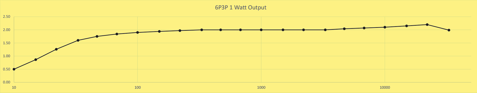
A four Ohm resistor was connected to the right input and music to the left. The function generator was set to 1 kHz sine wave and the input adjusted to give one Watt output. This was an input of 360 mV RMS from the high impedance output and 2 V RMS was seen on the oscilloscope. The top and bottom of the trace showed no sign of distortion. Measurements were made according to the E6 resistor sequence numbers (10, 15, 22, 33, 47, 68) for a sensibly even interval on the log X axis of the graph. Some cross-talk was noticed to the left channel especially between 1,000 and 3,000 Hz. This is to be expected with any common power supply and was the same for the EL34-B amplifier.
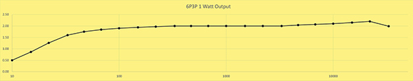
The output voltage for 1 Watt.
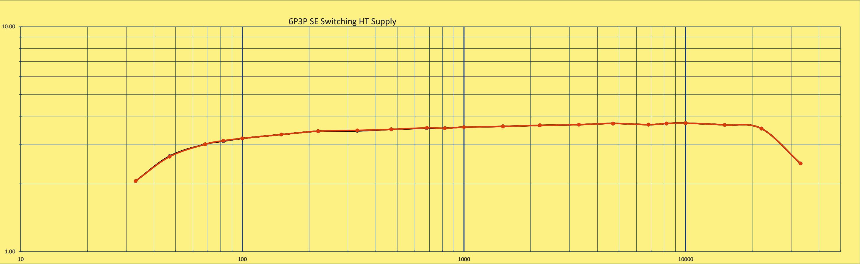
Following these measurements the function generator was reset to 1 kHz and the input voltage raised until the oscilloscope trace just showed a sign of distortion. The spectrum analyser showed low level lines at second and third harmonic. The output voltage was 3.77 V RMS equal to a power of 3.55 Watts. As the output valve has cathode bias the sine wave test gives a reading some 10% below the actual output under music conditions. Thus the true maximum undistorted output was 4 Watts. For actual listening the ear does not react to low level distortion at high volumes and so this amplifier probably does give 5 Watts before noticeable distortion is heard.
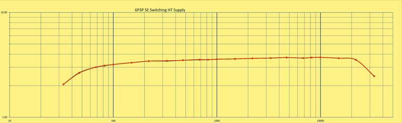
The undistorted output power 3.55 Watts. Black = left, Orange = right. They track almost perfectly.
The amplifier performed well on the Jamo speakers and on the Mission bookshelf speakers and ran for some five hours trouble free. Finally the amplifier was connected to the Wharfedale 9.1 speakers beside the office desk. The sound was clear and, of course, hum free. Silence between tracks. The next day the amplifier was in operation for just over an hour when a loud pop was heard followed by silence. Mains was entering the unit but there were no output voltages from the power supply.
The first response was not slow in arriving, the problem was not new. The request was that I measure the switching diode and opto-coupler. The images supplied had Chinese text and were of the top side of the power supply board. To make the measurements the board had to be removed from the case.
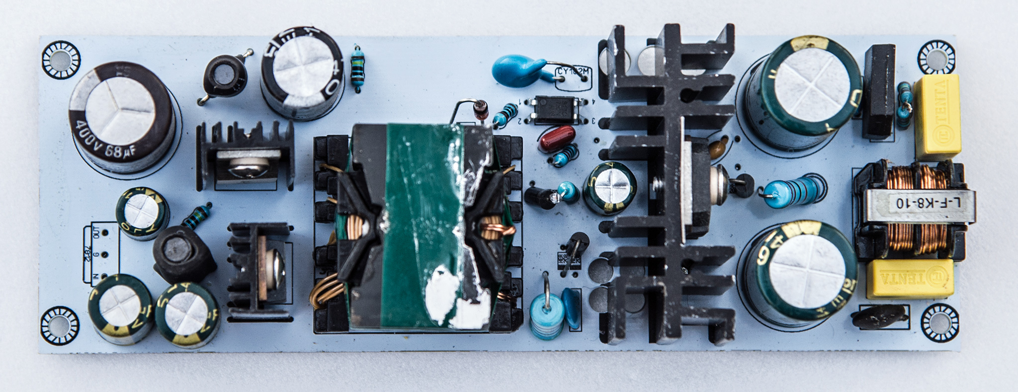
A quick look at the board showed the absence of any possibility of trimming the output voltage - hence the heater voltage not being set accurately to 6.3 Volts. Overall the construction is of a good standard but un-soldering the leads left the pads on the board free of solder and so it is possible that the solder had not wetted the board properly. As a test the ground pad was cleaned with a fibre-glass pen brush and solder applied to the clean pad. Straight away the solder flowed over the pad. The original manufacture has some dry joints.
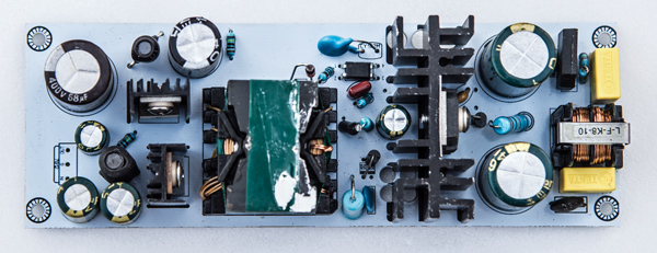
The power supply board. Mains input is at the right.
The switching diode was a dead short. The opto-coupler output had a resistance of 10 kΩ. These measurements were sent to the supplier via ebay.
The switching diode with a hole in centre of the ceramic case.
The next email requested a picture of the dead diode, see above.
Another quick turnround of emails. The text is as below.
hello dear customer
wish you have a nice day
change the C4D20120 diode and PC817 coupler if you can,
the machine is not so fragile like you imagine,
dont worry
Not what was expected. Checking the price of the components was the next step. The diode was quoted at £18.43 and the coupler at £0.53. The postage added another £12.00 making a total of £30.96 plus VAT.
In further communications was an offer to pay the cost of the new components and maintain a one year warranty or to pay the costs of returning the amplifier for a full refund. One cannot ask for more from a supplier. Components ordered, value refunded but not postage.
With some difficulty the components were removed. The solder pads were cleaned and re-tinned and the new components fitted. On test the power supply provided exactly 6.3 Volts DC for the heaters and on load the HT was 269 Volts. On switch-on the initial HT reading was over 400 Volts.
See also 6P3P Stereo Amplifier with conventional power supply.
|