|
This double triode with a maximum practical anode dissipation of 10 Watts looked just right to beef-up the ECC83 + ECC82 amplifier described here.
The author was sorting through some valves when the 33A/158M was found. Class A push pull low distortion came to mind. Limited data was available but sufficient to start work. The AC anode resistance is given as 4.5 kΩ and conventional wisdom suggests an output transformer impedance of twice ra. A suitable transformer was to hand - a VVT Transformers [★] no longer trading EL95 3 Watt SE.
A temporary arrangement of just one triode of the the 33A/158M was built and the grid driven by the function generator. At the maximum output of the generator (7 Volts pk-pk) the power produced was 250 mW. Moving the dummy load to the 16 Ω output tap on the transformer, to lower the effective impedance did little to improve matters.
Taking apart the Plessey PTR175 modulator yielded sub miniature valves and a couple of coupling transformers, as well as the pair of 2E26s. See here for a SE amplifier made from the 2E26. The article also has pictures of the original modulator.
The thought was that a single 6AT6 feeding the interstage transformer would provide both amplification and phase splitting. Initial testing of the interstage transformer had been encouraging, it was made for a military transceiver and the specs looked reasonable.
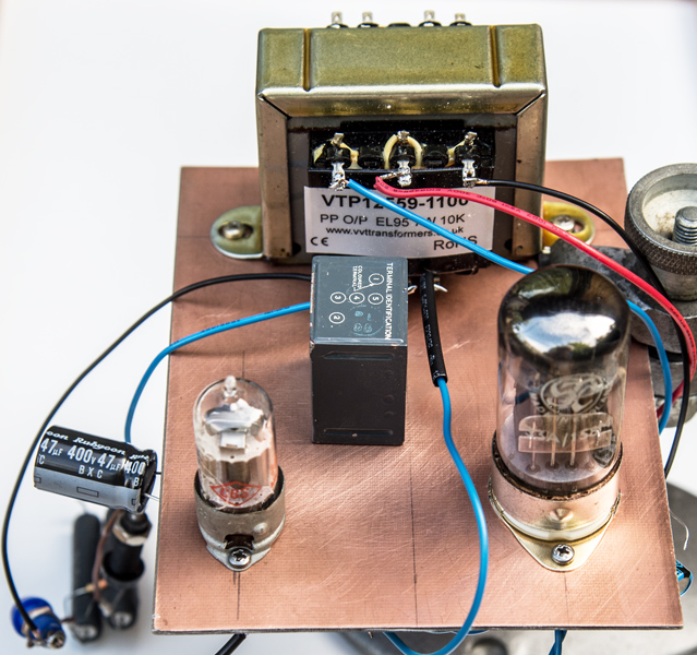
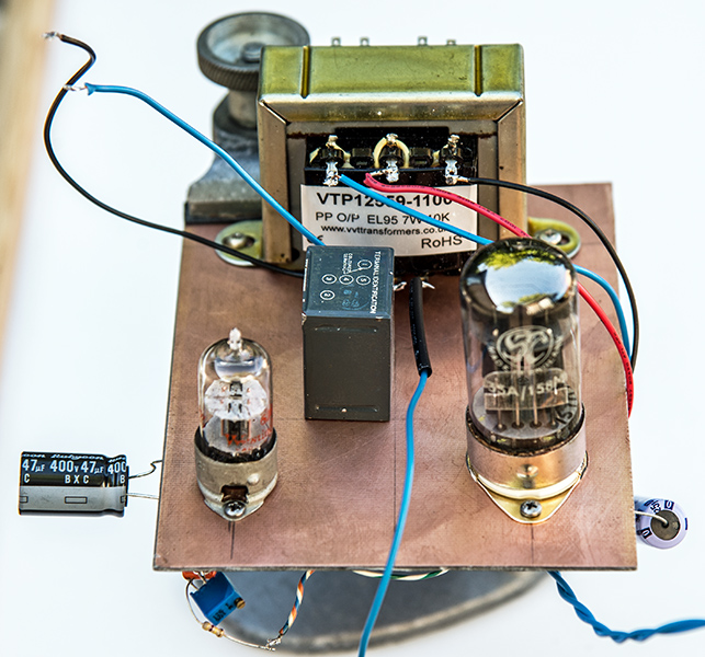
The prototype amplifier - top view.
A piece of double sided copper clad board was to hand to serve as the chassis. Holes were drilled and the soldering iron put to work.
With just the 6AT6 in circuit (see The Neophyte amplifier for the circuit) some tests were made. The output waveform from the transformer looked good on the 'scope and both halves produced identical outputs.
The 33A/158M was wired up next. The interstage transformer connected to the control grids through 1 kΩ grid stoppers and the centre tap returned to ground. The individual cathodes had 300 Ω resistors bypassed by 220 μF capacitors. The aim being to achieve 20 mA with a bias of -7 Volts.
With a low level 1 Hz sine wave as input the output across the 8 Ω load looked fine. Increasing the input started producing distortion before any appreciable power was being produced - disappointing.
Worse was to come. The frequency response was dismal at both low and high frequencies. Negative feedback was added but no appreciable improvement was seen and the distortion free output was 250 mW.
By chance the author was reading about the 33A/100A and the major characteristics suggested that the 33A/158M was virtually the same design but on a B8B base. The 33A/100A has a data-sheet, giving ratings for audio use. Output is 1 Watt with the two sections in parallel or 1.2 Watts when used in push pull class A. Moving to Class B, the output can be 12 Watts. The bias should be -13 Volts for Class A and -16 Volts for class B. Class AB1 should thus be around -14 Volts.
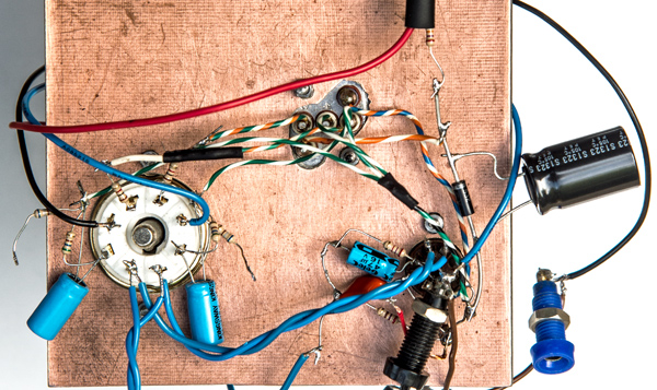
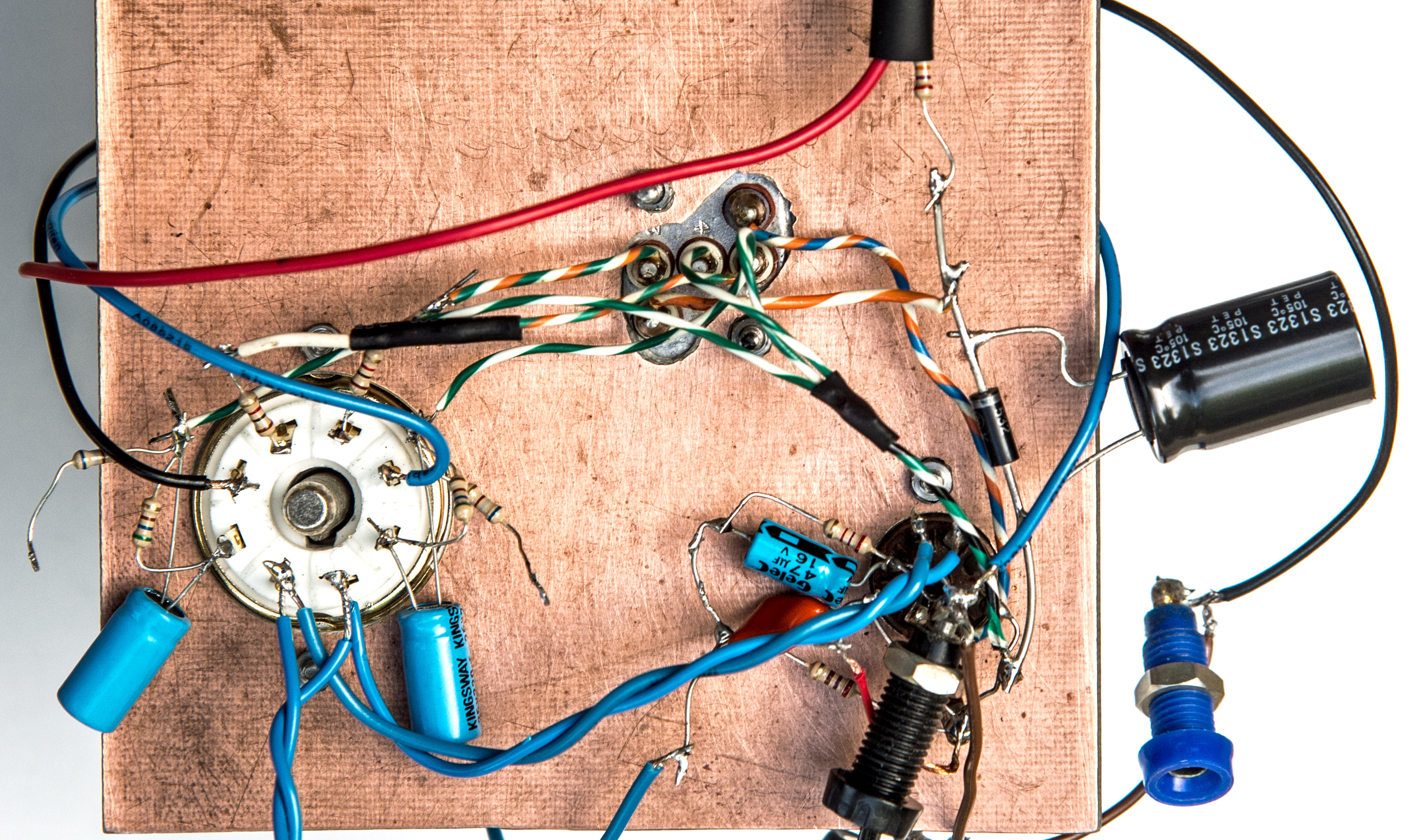
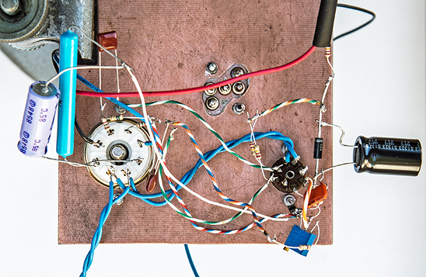
The prototype amplifier under chassis.
The single triode and transformer would need more work and for an output of a Watt was deemed too much effort for the reward. A more conventional phase splitter would be the next step.
The author had some NOS 6J6's in the workshop and a simple circuit was found. The 6J6 being B7G based would fit the existing valve holder. The 6AT6 circuit was removed and the new one built. The anode resistors were increased to 270 kΩ to use the 160 Volt supply.
Both cathodes of the output valve were connected to a single 1.2 kΩ resistor bypassed by a 1,000 μF capacitor. 14 Volts on the cathode was achieved with an HT of just over 200 Volts.
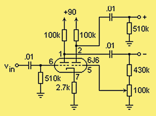
The 6J6 phase splitter with balance adjustment.
When powered-up the balance control was adjusted with the aid of the dual trace oscilloscope until both outputs matched.
With the bias set to 14 Volts without signal the output was 500 mW. The bias rising to 17 Volts after a short while.
Raising the HT to 300 Volts still kept the total current to below 25 mA and thus within the dissipation limits. The output was increased up to the point when the tops of the sine wave across the 8 Ω load were just flattening. The output was 1 Watt adjusting for cathode bias.
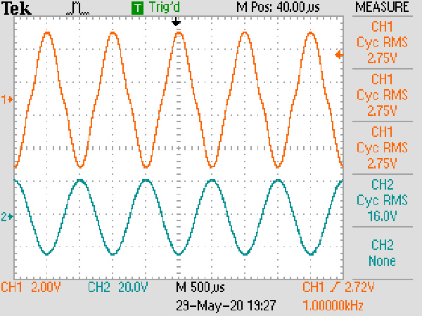
The waveform at 1 Watt and 1 kHz.
Slight cross-over distortion was present as can be seen below.
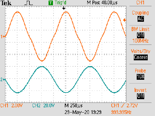
The slight cross-over distortion.
Next the maths function was activated and the balance control altered to see if a better balance could be achieved. It could not.
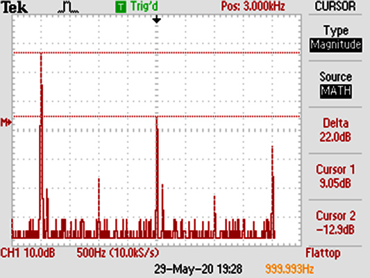
The FFT screen. The balance was adjusted for best cancellation of the second harmonic.
The output power was disappointing and the author was about to give up on the project when it was decided to replace the dummy load with one of the Mission speakers. The sound that came forth was much more than expected. From organ music for the bass and then Joan Baez for voice clarity the amplifier was a pleasure to listen to and the sound has the depth that was quite unexpected.
The underside of the prototype - not a pretty sight.
Time to return to the dummy load and measure properly. The input was set at 2.7 Volts pk-pk for an output to 8 Ω of 2.74 Volts RMS. At quiescence the cathode voltage was 16.22 Volts. A sine wave input raised that to 22 Volts. Trying to measure the instantaneous voltage suggested a value of 3 Volts. The transient output is a minimum of 1.25 Watts.

The full power output.
The 6J6 was NOS but the 33A/158M was of unknown origin and so that may account for the fact that the total current drawn is around 25 mA at 300 Volts or a DC input of 7.5 Watts - comfortable below the maximum dissipation for the power valve. The second harmonic was 44 dB down on the fundamental, third harmonic at - 22 dB, fourth at -44 dB and fifth at - 32 dB. A THD of just under 8%. No negative feedback has been applied. Using the 6AT6 as an input stage would allow for NFB to be applied.
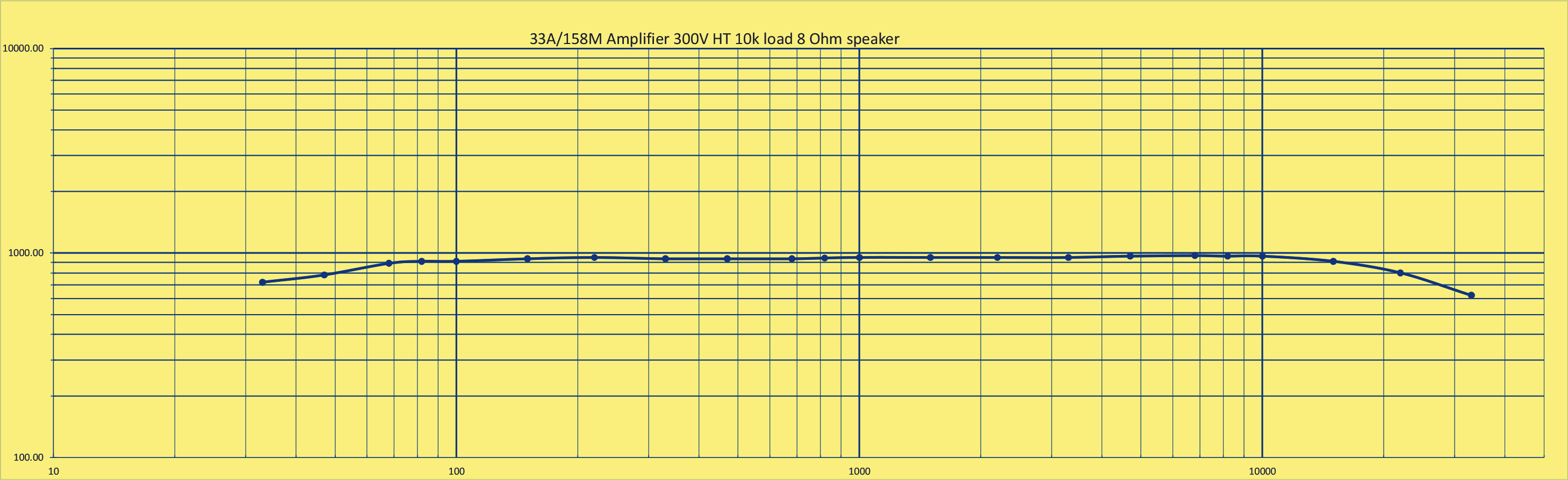
Testing the 6P14 parallel amplifier with a 1.5 Watt output for a DC input of 15 Watts per channel plus extra heater power puts this little amplifier project in context. A good frequency response and a sound quite loud enough for a room 4 x 7 metres.
The prototype with the now un-used interstage transformer.
The final incarnation of this project was the 6AT6 back in circuit driving the 33A/158M in parallel. The output was about half a Watt before the sine wave flattened. The transformer used was the 3 Watt EL95 SE from VVT.
The 33A/158M even at 300 Volts was drawing only 20 mA and so it is probable that the valve itself has lower emission than it should.
The conclusion is that the 33A/158M makes a pleasing push-pull amplifier of low output power but nothing special.
|