|
The basic principals described. Pulse modulation has many practical applications. One example of its use will be found in the Army No. 10 Set. The pulse-width system explained in this article is employed in the Pye television sound apparatus.
Of recent years pulses have become associated with radar to such an extent that one almost begins to believe that this is their only use. In fact, however, it is only one among many applications. Pulse technique was used in pre-war television to a very large extent and one has only to recall the line and frame synchronising pulses of the vision signal to realise their importance.
The use of pulses in sound transmission is not so widely known, however, and in certain cases it has important advantages. Before going into this, it will be well to clear up a possible source of misunderstanding, for the term pulse modulation is unfortunately often used in two different senses. It is used to describe the modulation of a radio frequency carrier by pulses and also for the modulation of a series of pulses by some, usually audio, signal. In the former case, the pulses themselves may or may not be modulated and in the latter the modulated pulses may or may not themselves be used to modulate an RF carrier.
In Radar, the carrier is modulated by pulses which are themselves unmodulated; in a communication system, the carrier is modulated by modulated pulses so that it is analogous to a sub-carrier system in which the pulses form the sub-carrier. In this article, pulse modulation refers to the modulation of the pulses by an audio signal.
If a series of recurrent pulses is generated, it is possible to employ it to carry intelligence by varying some characteristic of the pulses in accordance with the intelligence. One can vary the amplitude, the duration, or the interval between the pulses for this purpose. For the present we need consider only one of these - pulse-duration (or pulse-width) modulation.
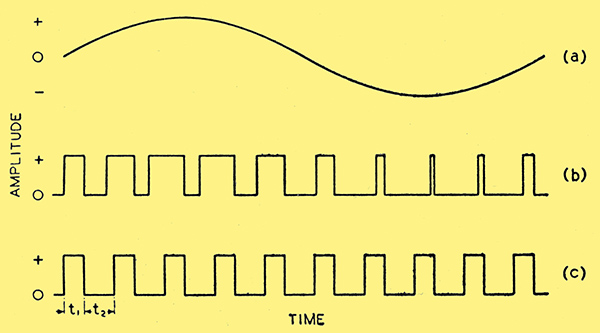
Fig. 1. This diagram shows a single sine wave at (a), and an unmodulated pulse train of ten times the recurrence frequency at (c). The modulated pulses are shown at (b); note that their duration depends on the instantaneous amplitude of the modulating wave (a).
Ten pulses of a recurrent un-modulated series are shown in Fig. 1 (c). Each pulse lasts for a time interval t1 and is followed by an interval t2 in which nothing is transmitted. The total time t1 and t2 of one pulse and one interval is the time of one pulse cycle, and the pulse recurrence frequency is the reciprocal of this. It is usual to speak of recurrence frequency or pulse frequency and of pulse duration or width. To say that the pulse frequency is 10 kHz and the pulse width is 40 μS. means that there are 10,000 complete pulse cycles a second and that one pulse cycle, therefore, lasts for 1/10,000 sec., or 100 μS. The interval between pulses is then 60 μS. Referring to Fig. 1 (c), in such a case t1 is 40 μS and t2 60 μS.
When such a pulse train is modulated in duration, the width of individual pulses is varied so that it is proportional to the amplitude of the modulating signal at that instant. This is shown in (a) and (b) of Fig. 1: (a) is one cycle of a sine wave and represents the modulating signal and (c) is ten cycles of the pulse waveform in the unmodulated condition; (b) shows the modulated wave.
In the case shown the trailing edges (i.e., the right-hand edges) of the pulses occur at the same time whether they are modulated or not, but the timing of the leading edges depends on the modulating signal. It is clear that as the waveform (a) grows, the pulses of (b) start earlier and earlier, so that their duration increases. The maximum width occurs when the voltage (a) has its maximum positive value. After this point the pulse width decreases, and when (a) swings negatively the leading edges of the pulses start later than those of the unmodulated ones. Therefore the pulses are shorter. The minimum width occurs at the negative maximum of (a).
Modulation Depth
If the unmodulated pulse width is t1 and it is symmetrically modulated, the maximum possible amplitude of modulation is also t2 and then the pulse varies between the limits of t1±t1, or from zero to 2t1. This is, of course, provided that the pulse t1 is equal to or less than the interval t2 between unmodulated pulses. This represents 100% modulation.
In practice, such deep modulation is undesirable because it means the disappearance of the pulse on the negative peak of modulation and in addition very narrow pulses demand an excessive frequency band for their transmission. In general, a modulation depth of 80% is about the maximum allowable. For the case quoted of 40 μS pulses this would mean a variation of 32 μS, so that the minimum or maximum pulse lengths would be 8 μS and 72 μS respectively.
It will be observed that the system virtually samples the modulating signal at intervals and in consequence the signal is not transmitted continuously. There is a minimum number of pulses needed for each cycle of the wave to be transmitted, therefore, if faithful reproduction is to be obtained. One would expect this would be at least several hundred, but in actual fact no more than three pulses are needed and with some care quite good results are obtainable with two pulses per cycle only!
Usually, one takes it that the minimum pulse recurrence frequency is three times the highest modulating frequency, or some 30 kHz for high-fidelity reproduction or 9 kHz for ordinary commercial grade telephony.
So long as the sides of the pulses are vertical, the linearity of the apparatus handling the modulated pulses is unimportant; it is possible to use amplitude filters without causing distortion and often with a considerable reduction of noise. This is analogous to the methods frequently adopted in television reception of limiting the sync pulses to reduce the effects of noise and other interference.
The disadvantage of pulse modulation is the wide band of frequencies needed for its transmission. The highest frequency needed, is of the order of the reciprocal of the narrowest pulse duration. In the example above this was 8 μS, so that the highest frequency is about 125 kHz. This is very high for a maximum modulation frequency of some 3-5 kHz only. The bandwidth radiated is, of course, double this for the usual double sideband transmission, so that the system is not one which is ever likely to be adopted on ordinary wavelengths where the space available is strictly limited.
Multi-Channel Systems
It is, however, of very great advantage on very short wavelengths where ordinary methods of modulation are difficult and where the bandwidth needed becomes unimportant. It also lends itself well to multi-channel working.
If the unmodulated pulse duration is considerably less than the interval between successive pulses, then another series of pulses, representing another channel of communication, can be inserted in these intervals. This is what is done in the Pye television system. The sound pulses are of 3 μS duration and vary between 1 μS. and 5 μS. The whole vision signal, representing a second channel, is inserted in the gaps between them.
Before concluding, something should be said on the demodulation of the pulses to produce the audio-signal again at the receiver. With a single channel, the detector output is of the form of Fig. 1. (b) and it is necessary to produce from this the original wave (a). Surprising as it. may seem, this can be done with nothing more than a simple low-pass filter. Mathematical analysis of the wave (b) shows that it is nothing but the wave (a) with the addition of a large number of higher frequency components of which the lowest is the pulse recurrence frequency and it is only necessary to filter out all these to obtain the original wave.
With the multi-channel systems, it is first necessary to sort out the pulses for each individual channel. In the Pye system, the pulses of the sound channel are of greater amplitude than the vision signal and can be separated by a simple amplitude filter. Passing the separated pulses through a low-pass filter then produces the audio signal.
|