|
A practical super-regenerative receiver.
In case anyone is thinking of telling 'Cathode Ray' that he has become nothing more than an armchair philosopher, he hastens to say that he is quite aware that the intellectual delight of studying modern radio developments is not fair compensation for the loss of practical experience. So here, for a change, is something to do at home. Something not too difficult as a knock-up after being out of the game for years and years. And it is in response, too, to the interest shown by so many readers in my notes on the super-regenerative receiver (June, 1946). As I pointed out then, the great merit of the super-regen is that it gives so much for so little. Most people no doubt realize how much the focus of interest has shifted to the very high frequencies, and may want to explore them, but hesitate to embark on constructing elaborate equipment with very meagre practical information. The super-regen is just the thing. The valve requirements could hardly be less - one solitary triode, of almost any reasonable type. And the rest - a handful of components obtainable with almost equal ease from the pre-war junk box or the post-war dealer.
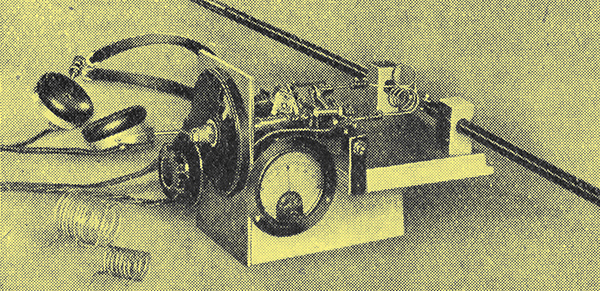
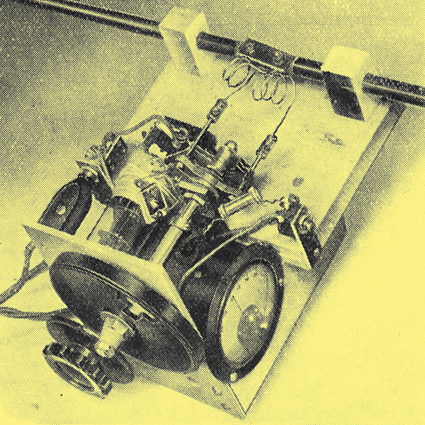
An extemporized VHF super-re-generative receiver.
It has other advantages besides cheapness and ease of construction. The sensitivity is extremely high ; yet there are no critical adjustments or setting-up. The selectivity is so low that tuning is quite as easy as on the medium broadcast band. Fortunately high selectivity of VHF is seldom needed - yet on most of the bands. The unfairly maligned background noise not only indicates when the set is working properly, but simplifies tuning to unmodulated carrier waves, which show up as 'holes' of silence. Finally - and this may be news to some - it works with either amplitude modulation or frequency modulation, and indicates which is which. So altogether it is just about ideal for a preliminary survey of the VHF band.
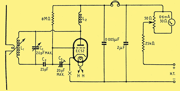
Fig. 1. Circuit diagram of the receiver shown above.
To forestall scornful merriment, may I explain that the particular embodiment of the super-regenerative principle shown is of rough bread-board construction, lashed up from a few scraps of wood and components that happened to be around. There is no reason why anybody who wants a more finished looking job should not enclose it in a tastefully designed case; in fact, if it is to be used out of doors, or in a car, that would be the sensible thing to do. There is plenty of latitude as regards the circuit and the component values, and especially the power supply. For this particular set, with a consumption of 0.43 A at 6.3 V and about 0.5 mA at 80 V, an AC mains unit was rigged up from spare components (including an old Class B driver transformer) to the circuit shown in Fig. 2.
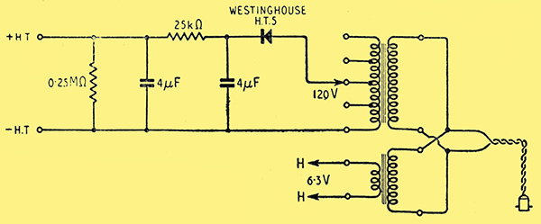
Fig. 2. A power unit for the receiver, composed of oddments, including a disused Class B driver transformer for HT.
Possible alternatives, according to the sphere of action and the triode used, are:-
- Battery LT and vibrator HT
- Battery LT and HT
- AC LT and Battery HT
- Tappings of the power supply of a broadcast receiver or AF amplifier used to obtain loudspeaker reproduction.
The first three options would be suitable for in car use.
In the last case the super-regenerative receiver can be regarded as a VHF adapter, its output being suitably connected to the gramophone terminals of the main set.
The circuit is a self-quenching Colpitts oscillator. The optimum quenching frequency is not critical, but increases with the radio frequency. Taking the grid leak to +HT raises the QF and at the same time encourages quenching. In fact, with a high-slope valve, like the EC52, quenching may be rather excessive, as shown by the anode current falling to perhaps only 0.1 mA. So the small preset capacitor C3 is used to control oscillation.
Although a geared tuning drive is shown, it is not really essential. But it is necessary to use a non-conducting extension spindle, since neither side of the tuning condenser is earthy.
Tuning inductors, L1, are pieces of bent wire held in screw connectors on the supports of the variable capacitor. Examples:-
- 37-57 MHz: 9 turns 2 cm dia, 3.5 cm long.
- 65-100 MHz: 4 turns 1.7 cm dia, 2.3 cm long.
- 90-140 MHz: 1 turn 4 cm dia.
- 110-170 MHz: Short circuit.
The first includes the Alexandra Palace sound and vision (41.5 and 45 MHz respectively) and the second the BBC. experimental FM on about 90 MHz and police transmitters (which, of course, on identifying, one will, in accordance with the terms of one's licence, immediately tune out!).
For higher frequencies, the policy to adopt is to eliminate leads in the tuning circuit, to remove C3, and, if necessary, to cut out C1 altogether, tuning by means of a variable C2.
The choke L2 is not critical; the one used here has about 70 turns of 40 SWG on a ¼ in tube. If moving the phone and power leads about provokes signs of affecting the tuning, another choke may be inserted at X.
Aerial Arrangements

Fig. 3. Aerial coupling coil, connected between camera tripod legs forming adjustable dipole aerial.
The most satisfactory dipole aerial is one constructed of a pair of tubular metal telescopic camera tripod legs. Not only do they contract to a reasonable size when out of use, but their length can be adjusted to resonate at any frequency over a wide band. The top ends are provided with lugs through which screws can be passed to serve as terminals for a coupling coil of one or two turns and also to hold strips of insulating material as a mechanical support (Fig. 3). The legs are attached to the baseboard by blocks of wood with holes that are a tight enough fit to be secure, but allow the dipole to be twisted in them so as to vary the coupling with the tuning coil.
When the set is switched on, the anode current first rises; then drops once at the start of oscillation, and again at the start of quenching. The characteristic rushing sound can then be heard. If only one drop occurs, oscillation is not fierce enough to quench itself and appropriate action - such as raising the HT or reducing C3 must be taken.
The easiest way to calibrate the tuning scale is with an absorption wave-meter, held no closer to L1 than is necessary for the meter to show a perceptible flicker when the wave-meter is tuned through resonance. Lacking a wave-meter covering the desired band, one can make one by mounting a pair of parallel wires, say 1 n apart, and bridging them at two places separated by a distance equal to 0.48 λ. One end of this long rectangular-shaped loop of wire is brought near L1, and C1 is varied until absorption is shown. But remember that this sort of wave-meter responds to harmonics of its fundamental wavelength.
The aerial is tuned in the same way, as if it were an absorption wave-meter, by noting the setting of C1 at which maximum absorption is indicated by the rise in anode current; and then shortening or lengthening the aerial rods as required. One can make sure that it is the aerial that is absorbing by touching one or both of its ends and seeing that the meter responds. If no meter is available, aerial resonance can generally be detected by a rise in noise. The aerial effectively covers a band of at least several MHz each side of spot tune, and brings in any but weak signals outside that band.
Aerial Exploration
The advantages of a tiny set that can be connected to its power source by long flexes, or direct to portable batteries, is that one can examine the polarization and direction of incoming waves by turning the aerial around in all directions. Alternatively, the aerial can be connected to an 80 Ω flexible VHF twin-wire feeder, allowing the set to be fixed. In which case it is convenient for listening purposes to couple its output to the 'Gram'. socket of a broadcast receiver, through a transformer. A step-down of several-to-one is advisable. And, of course, when one is not interested in exploring fields (electromagnetic) the receiver can be connected by feeder to a fixed aerial on the roof or other elevated spot. But it is only fair to point out that such an arrangement is likely to radiate perceptibly over a sufficient radius for it to be deemed by the GPO (and perhaps by neighbouring VHF explorers) to be a transmitter.
This simple set demonstrates very effectively the relative immunity of the super-regenerative receiver from ignition interference, especially if a television receiver is available for comparison; and also its AGC properties at all signal strengths great enough to suppress the background noise.
FM transmitters can be distinguished from AM because the modulation becomes almost or entirely inaudible when the receiver is tuned exactly to the carrier frequency. To hear it, the receiver has to be mis-tuned slightly either way, when the variations in transmitter frequency on the slope of the receiver response curve give amplitude variations. This ancient method may seem rather crude, and it is true that either the efficiency is small or the distortion is large (by very-high-fidelity standards). But the super-regen is sensitive enough to stand some loss of efficiency, and makes no claim to high fidelity in any case.
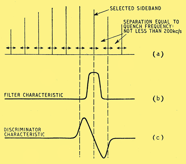
Fig. 4. In a super-regenerative FM amplifier, its frequency-modulated output sidebands (a) are transposed to a much lower frequency and passed into a filter (b) which selects one for applying to a FM discriminator (c).
While on the subject of FM it may be worth mentioning that a super-regenerative stage has been found very effective as an amplifier. I have not actually tried it in this role, but suggest it as an interesting line of experiment to follow the set just described when its possibilities have been exhausted. The theory, briefly, is that a super-regenerative oscillator is synchronized by an incoming signal of as little as 10 microvolts. Being modulated by the quenching, the oscillator has a series of sidebands spaced at intervals of fq (the quenching frequency), so each of these is frequency-modulated by an incoming FM carrier. If fq is considerably higher than the frequency deviation of the carrier - say 200 kHz - so that any one sideband can be selected to the exclusion of all others, it can be applied to the usual FM discriminator (Fig. 4). In practice it appears to be necessary to use a frequency - changer to lower the frequency of the super-regenerative output. And a buffer stage is desirable in front to prevent radiation. So it begins to approach the orthodox superhet in complexity. But with an equivalent amount of gear it seems likely to have a higher sensitivity and freedom from ignition interference. (The ordinary FM receiver is not too good at coping with the latter; but a super-regenerative stage in front ought to reduce it to manageable proportions.) Whether you ultimately go, in for this fancy hybrid or stick to the plain superhet, however, the single-valve super-regen. is a good introduction to the VHF band.
By no other means is it possible so easily and so cheaply to obtain first-hand knowledge of what is still terra incognita to many wireless men.
An extemporized VHF super-re-generative receiver.
|