|
A re-assessment in the light of recent developments.
One can hardly expect anything, I suppose, to keep on being sensational for 24 years, but it does seem to me that the super-regenerative receiver deserves rather more publicity than it gets. Its performance really is sensational. A good single-valve super-regen is as sensitive as almost any receiver can be, regardless of the number of valves. So far from falling of at the ultra-high frequencies, it works better. It includes automatic again control that would need a multi-valve superhet to equal. On top of all that, it deals effectively with interference of the motor ignition type that is so troublesome on the television waveband.
From the fact that the manufacture of all other types of receiver has not ceased, you are correct in deducing that the super-regen has snags. Those usually held up against it are:-
- lack of selectivity,
- noisiness,
- radiation, and perhaps,
- uncertainty or freakishness of results.
All of these can be largely or entirely overcome. The real objections, to my mind, are:-
- that its performance, which is best at the very high frequencies (where other types of receiver tend to fail), falls off at the lower carrier frequencies
- likewise at high modulation frequencies; and
- that it distorts deep modulation rather badly.
(a) and (c) knock it out for broadcast reception, and (b) for television. So to the man in the home the super-regen is not 'news'. It didnbt even get much credit for its war service as the heart of the most-produced radar equipment - IFF and beacons - as well as in innumerable 'walkie-talkies'. Incidentally, its use for IFF, where the utmost stability and reliability was essential, disposes of objection (4) on the above charge sheet. There are many other jobs at which the super-regen could be usefully employed if it were better known and understood.
The trouble is that, although the super-regen circuit is simple in appearance and (up to a point) in theory, attempts to produce anything like a comprehensive theory of its action have invariably led to the most appalling mathematics, with each authority arriving at an entirely different and often contradictory result. So the practical man, finding it hopeless to think of designing a super-regen on a rational basis, has tackled it by trial and error, has unleashed a variety of noises and obscure effects unrivalled in any other branch of the art, and in disgust has made a superhet instead.
One reason for this state of things is that the super-regenerative receiver works in quite a different way from any other sort, superficial resemblances notwithstanding. Another reason is that its performance depends on so many variable quantities that it would be an endless job to give a complete account of all the possible combinations; so anyone who sets out to analyse it has to make some assumptions. Different authorities have made different assumptions; hence the conflicting results on record. This is not very encouraging for the ordinary reader, so what I am going. to try to do is to give a reasonably simple account of how it works, the conditions that give the best results, and some practical suggestions.
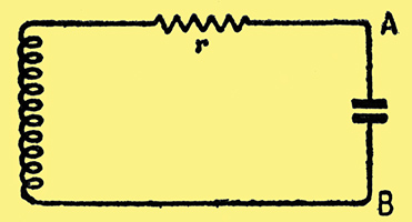
Fig. 1. Simple tuning circuit, in which r represents the effective resistance. In a superregenerative receiver, r is made to alternate rapidly between positive and negative.
We begin with a simple tuned circuit, Fig. 1. The resistance r is not usually there as a visible component; it represents the unavoidable losses, chiefly in the coil. When a signal voltage arrives, Fig. 2 (a), of the frequency to which the circuit is tuned, it builds up a comparatively much greater voltage, Fig. 2 (b), across AB, which is then applied to the input of an amplifier, etc. The number of times greater is denoted by Q. For an average sort of tuned circuit by itself, Q is of the order of 100. When the signal stops, the voltage across AB dies away as shown.
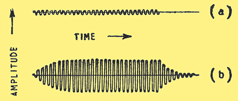
Fig. 2. If r in Fig. 1 is positive, the arrival of a signal voltage (a) in series with the coil causes a magnified voltage (b) to build up across AB. When (a) stops, (b) dies away gradually. This is the normal unassisted behaviour of a tuned circuit.
Reducing r increases Q and also the amount of the build-up and the time taken to die away. By the use of reaction, r can be reduced to zero and even made negative. What happens then is that any voltage, however small or short-lived, starts oscillation at the natural frequency of the tuned circuit, and the oscillation continues to grow, in the manner shown at the left-hand side of Fig. 3 (a), until something happens to reduce the negative r to zero.
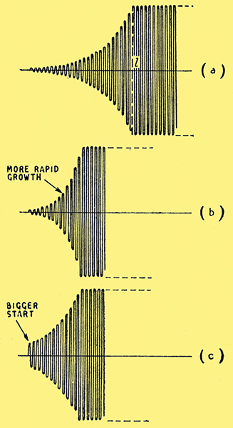
Fig. 3. When, with the aid of a valve and positive feedback, r in Fig. 1 is made negative, oscillation builds up (a) until, at l, it is checked by the valve reaching its limit. Either a greater negative r (b) or a bigger start (c) makes oscillation reach the limit sooner.
That something is generally the valve being driven to the limit of amplitude that it can handle. After that, the oscillation continues steadily at constant amplitude, as shown from the time marked l onward. In practice, of course, the pre-l and post-l phases are not so clear-cut, but merge into one another.
The way the oscillation grows while r is at a constant negative value is the same as that by which money grows when subject to compound interest; each cycle is a certain percentage larger than the preceding one. The percen- tage depends on r; the greater the negative r the greater the percentage growth, and the quicker the oscillation will reach its limit from a given start, Fig. 3 (b). Another way by which the limit can be reached in a shorter time is by giving a bigger start, as in Fig. 3 (c) (which is just (a) with the first few cycles omitted). Relative to Fig. 3 (a), (b) shows the result of a higher rate of interest, and (c) the result of investing a larger capital. Some numerical examples may help to make it clear:-
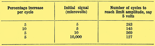
Fig. 3 is the key to super-regenerative action. Armed with it, we can tackle a receiver circuit, Fig. 4. Apart from the quench oscillator, this is a very simple 1-valve receiver with reaction.
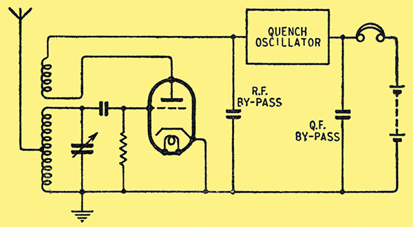
Fig. 4. Simple super-regenerative receiver circuit.
Assuming reaction is adjusted to the edge of oscillation (as it generally is in 1-valve receivers), r is almost zero, and a substantial increase in anode voltage will bring it well into the negative region, while an equal reduction will bring it well into the positive region. That is precisely what the quench oscillator does alternately, at a frequency which must be much less than that of the RF carrier wave, but greater than that of any modulation of the carrier. The precise frequency to adopt, within these limits, is one of the great super-regen controversies. Another thing that has a profound effect on the performance (and accounts for many of the discrepancies between different treatises on the super-regen) is the waveform of the quench oscillator.
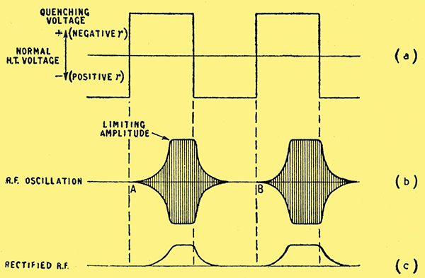
Fig. 5. Application of a square quenching wave (a) causes RF oscillations to build up and die away as at (b). The RF is rectified in the super-regen valve giving unidirectional pulses (c), and it is the variation in the size of these that is audible. For example, the second one shown here is larger than the first, indicating that the signal at B must have been stronger than at A.
Although not at all typical of actual practice, a square wave is the simplest for explanation. Consider, then, what happens when the quenching wave, Fig. 5(a), goes through its cycle, beginning with the negative half, which keeps the valve well off the oscillation point. There is no incoming signal, shall we say; so the only voltages present in the tuned circuit are the very small ones due to random motion of electrons, called inherent circuit 'noise', of the order of a microvolt. These are completely irregular, and only a very small proportion occur at the frequency of the tuned circuit, which consequently is very little excited by their presence. What we have, then, is a very small and very erratic oscillation in the tuned circuit.
When the quenching oscillator clicks over to its positive half-cycle, oscillations, begin to build up, starting at the level at which by pure chance the noise voltage happens to be just then. Whether they will reach the limit during the half-cycle depends on:-
- the noise voltage at the start;
- the rate of growth (which in turn depends on the quenching amplitude and other circuit conditions);
- the limit amplitude;
- the number of RF cycles in one QF half-cycle (i.e., the ratio of radio frequency to quench frequency)
This is where one begins to see that the problem may soon get out of hand; but there is no need to take fright just yet. In a given receiver, (2)-(4) are all fixed, and it is easy to see that in order to ensure even the smallest voltage building up to the limit in every quenching cycle it is only necessary to make the QF low enough. Let us do that, then.
Oscillation continues at the limit for the rest of the half-cycle, after which r is made positive again. Just as the rate of growth was proportional to the negative value of r, so the rate of die-away depends on the positive value. Assuming the two are roughly equal, the oscillation may be expected to have died down to noise level before the next dequenching half-cycle begins. When it does, the noise voltage at that instant will in general be different from what it was at the start of the previous (or any other) dequenching half-cycle; so the build-up will be quicker or slower accordingly.
Any sound that is heard in the phones is produced by the current, indicated in Fig. 5 (c), due to rectification of the bursts of RF if these bursts occurred at an audible frequency they would, of course, produce a loud note of that frequency. But they occur at QF, which we have assumed (for one reason which is now clear) to be higher than audibility. The sizes of the bursts are varying, however, according to the noise voltages that happen to exist at the moments when the quench voltage goes from negative to positive.
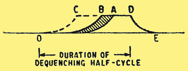
Fig. 6. When only noise is stimulating the receiver, the size of the rectified pulses varies to a certain extent, shown shaded. A relatively strong RF signal brings it, say, to C. Growth starts at O every time, but with a weak start is not big enough to show in a diagram until some way towards E.
In Fig. 6. OADE represents a rectified burst following the least possible noise voltage, and OBDE one following the greatest noise voltage; so the maximum variation in size is as shown shaded. As the variations within this maximum are erratic, a completely formless sound, like gramophone record scratch, is heard. It indicates the enormous amplification of the super-regen, for there are few superhets, even, that amplify enough at very high frequencies to reveal circuit noise so strongly.
However, this sound, interesting theoretically and useful for indicating that the super-regen is super-regenerating, regarded as programme material fails to grip the attention for long; so we next consider what happens when a carrier wave is tuned in. If this carrier wave is unmodulated, and much stronger than the noise, the starting voltage is practically the same at every quench cycle, so every burst is the same size (say, OCDE in Fig. 6) and no sound is heard. When the carrier wave is modulated, the sizes of the bursts are made to vary at audible frequency.
If you have read 'Pulse Modulation' in the April issue you will agree that the super-regen process is remarkably like pulse length modulation. The super-regen valve generates RF oscillations; the quench oscillator generates fat pulses which modulate the RF into what I call wave pulses; the incoming signal modulates the effective length of the wave pulses; and the super-regen valve demodulates the modulated wave pulses, extracting the modulation frequency.
I hope the fog has now cleared away sufficiently to reveal the reasons for most of the peculiarities of the super-regen:-
Sensitivity
If a tenth of a penny had been invested at 5% per annum compound interest in the year 1 AD it would today have grown to £100,000,000,000,000,000,000,000,000,000,000,000,000 or roughly a lump of gold as big as the whole world for every 10 seconds through all those years. As the super-regen amplifies on the same principle, a phenomenal gain is only to be expected. Its voltage amplification is limited at one end by the size of the smallest possible voltage (i.e., noise) and at the other by the power-handling capability of the valve, and is of the order of a million. That is assuming the oscillations have time to build up to the limit. The lowest QF that does not cut into speech frequencies is, say, 10 kHz, so half a cycle lasts 50 μS. judging from the examples already worked out, it looks as if we ought to allow for several hundred RF cycles in this time; say 500. That puts the lowest RF for most effective performance at about 10 MHz (30 metres wavelength). The lower the RF, the stronger should be the quench oscillation, in order to build up within the limited number of RF cycles.
On the other hand, if the RF is very high and/or the quench is very powerful, it is better to increase the QF, in order to get more build-ups into a given time. The QF giving the most amplification is that which just allows time for full build-up and die away in each of its cycles.
AGC
The numerical examples showed that a 1,000 fold increase in signal input only reduced the number of build-up cycles from 269 to 127. Let us elaborate this a little. It is the variations in signal strength, due to modulation, that are effective in producing audible output. Those variations can be measured by the variations in the number of cycles necessary to build up to the limit. Let us suppose both signals in question are modulated 50%, as follows:-
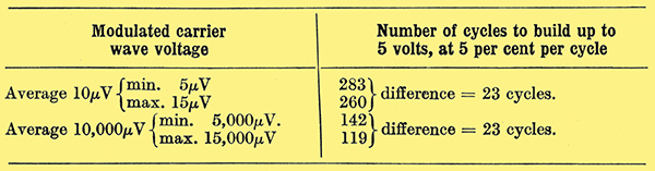
So these signals of vastly different strength, when equally modulated, give exactly the same output! AGC action is therefore theoretically perfect. In practice it is not exactly so, because the non-linearity of the valve upsets the compound interest law slightly, and also very weak signals have to compete with noise. Fig. 7 is an actual measured input/output curve.
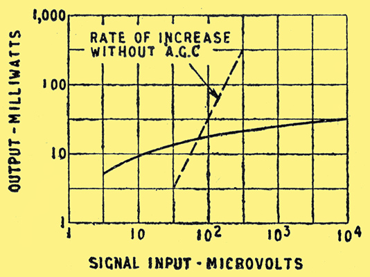
Fig. 7. Actual input/output curve of a typical super-regen receiver, showing AGC characteristics with 30% modulation. The dotted line, for comparison, shows the characteristic of a receiver without AGC.
Noise
The origin of the characteristic rushing sound of super-regeneration, and the reasons why it disappears when a relatively strong carrier wave is tuned in, are, I hope, now clear. But suppose the QF is increased, or its amplitude on the negative side reduced, so that oscillations have not time to die away, but are still several times stronger than the noise voltage when the next positive QF half-cycle is due to begin. Then the starting level will be this constant oscillation voltage rather than the erratic noise voltage; and the characteristic sound will be absent. That may be hailed as an advantage; on the other hand, when the receiver is tuned through a carrier wave its self-oscillations will cause whistles by beating with the carrier. The situation is even more complicated, because as the tuning is varied the oscillations produce audible stroboscopic effects with multiples of the quench frequency, rather like the strange behaviour of the wheels of moving vehicles seen in the cinema. Without going into all the gruesome details, you may be able to see that there is plenty of basis for the weird effects obtainable with super-regen receivers. The surest way to keep clear of them is to keep the RF high and the QF low.
Interference Suppression
Interference of the 'click' type, caused chiefly by motor ignition systems, is generally the most prevalent on the VHF waveband, for which the super-regen is most suitable; and electrically it consists of very intense but short-lived and isolated pulses. Looking at curve OCDE in Fig. 6, representing a quench cycle during reception, any clicks during the period CD find a receiver already saturated with oscillations of maximum intensity, and therefore practically dead to outside influences. During DE the oscillations are being suppressed. Just at O the receiver is extremely sensitive, but the chance of a click happening exactly then is very small. From O to C the effect produced by interference gets less and less. It is fair to say, then, that most of the interference is suppressed, and very few of the clicks get through with any serious strength.
Distortion
Putting together figures we have already had, we see that a 10,000 μV signal growing at 5% per cycle builds up to 5 Volts in 127 cycles, and that when modulated to a depth of 50% the positive peaks advance the build-up by 8 cycles while the negative peaks retard it by 15 cycles. The output modulation wave will therefore be lopsided, and the distortion rapidly grows worse as the depth of modulation is increased. It is good enough for intelligible speech, however, if the modulation is kept within about 80%, but rules the super-regen out for high-quality reproduction.
Selectivity
With the square quenching wave we have been assuming, the build-up time is determined by the amplitude of whatever is in the input circuit at the moment of dequenching. The selectivity is therefore no better than that of the single tuning circuit under quench conditions; that is, it will be just about as poor as with one tuned circuit and no reaction. That may not be at all a bad idea in the VHF or UHF bands, where searching with a highly selective receiver is like looking for the proverbial hay-shrouded needle. But to refute the charge that this very low grade of selectivity is the best the super-regen can offer, it may be pointed out that there are other ways of organizing it. If the quenching voltage, after it has had time to suppress oscillation, is eased off so that for a little while before the dequench point the circuit is near the edge of oscillation, signals of exactly resonant frequency are built up by the ordinary reaction process and are all ready to kick off oscillation with a flying start, whereas off-tune signals and noise are not thus pre-amplified. Selectivity and signal/noise ratio can be improved in this way by using a sine wave quench (which anyway is more natural than a square one) of the lowest possible QF (already recommended), and the minimum quench voltage and maximum reaction that will work properly. Instead of clicking suddenly over from high positive r to high negative r, as it does with a square quenching wave, the circuit spends more of its time with r near zero.
Radiation
It is obvious that the Fig. 4 circuit will radiate furiously, a fact of which use is made in transceivers; if it is necessary to prevent it, a preliminary RF stage with proper screening is the remedy. [*] See for example O.J Russell, Super-Regeneration, Wireless World, December, 1944.
Erratic Performance
Some of the causes have appeared already; too high a QF is about the commonest. Another is trying to make one valve do everything, including generating the quenching wave. In Fig. 4, the square box will normally contain a valve oscillating at QF, and appreciable power is needed to quench the super-regen valve in its anode circuit. But it is a good stable job. Economizing by quenching at the grid introduces complications, and a larger share of skill or luck is needed to get good results.
Conclusion
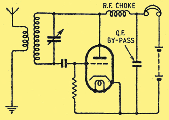
Fig. 8. Flewelling, or self quenching, super-regen circuit.
Lastly, a few remarks on some special sorts of super-regen. What is called the Flewelling circuit (Fig. 8) is the ultimate in economy and simplicity. It is adjusted to oscillate so furiously that the accumulated negative bias chokes itself off, and it has to wait until the grid capacitor has discharged before it can start again. If it does this a super-audible number of times per second, it combines the functions of RF oscillator and quenching oscillator. The QF depends mainly on the vigour of RF oscillation and on the values of grid capacitor and leak. The grid voltage goes through working cycles rather as shown in Fig. 9; and they look almost ideal for encouraging selectivity.
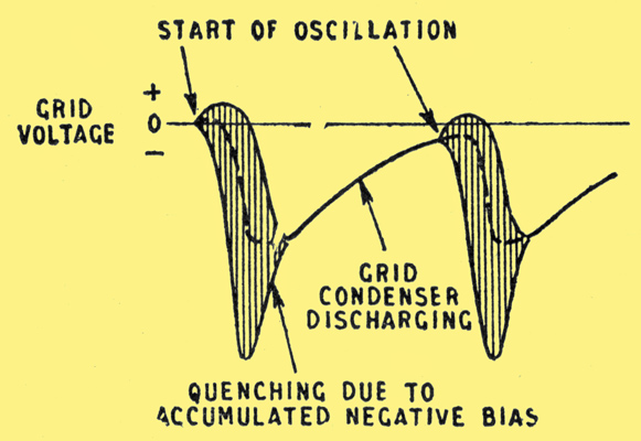
Fig. 9. Variation of grid voltage during two quenching cycles in the Flewelling circuit. The dotted line shows the average grid voltage during oscillation.
The Flewelling is not a very flexible circuit, but it is quite a good one for working on a fixed and very high radio frequency.
Personally, I think the most satisfactory 1-valve super-regen circuits are those using frequency-changer valves.
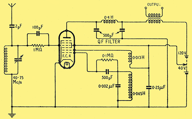
Fig. 10. Recommended super-regen circuit, using a frequency-changer valve.
Fig. 10 shows one built around an FC4 octode, but heptodes can be used, and no doubt triode-hexodes, too, with slight modifications. The first two grids, normally used for the local oscillator in a superhet, are employed to generate the QF; and the RF goes in, also quite normally, at the control grid. At least, it looks normal for a superhet but quite abnormal for a super-regen, as there is apparently no reaction! Nevertheless, it works, at VHF, because the effective cathode is somewhere between the visible cathode and the control grid, and stray capacitances cause the circuit to oscillate in the Colpitts manner.
Everything so far has been based on the assumption that oscillations are allowed to build up to the limit. If, on the other hand, the QF is raised so high that they never have time to do so, the performance is quite different.
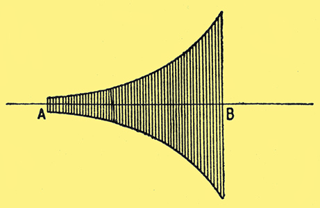
Fig. 11. In the non-limited or linear type of super-regeneration, the dequenching half-cycle, starting at A, stops at B, before the limiting amplitude has been reached.
In Fig. 11, if oscillation is started from, say, 10 μVolts at A and allowed to grow at compound interest, say, 5%, until B, each cycle will be 1.05 times greater than the one before it. Suppose there are 150 cycles. Then the amplitude of the final one will be 10 × 1.05149, which is 10 × 1440. If the starting level had been, say, twice as great, the output would have been double, too. Output is exactly proportional to input. Working this way, there is less amplification per quench cycle, but more quench cycles, less selectivity, no AGC action, and no distortion. In various ways this suits IFF receivers, which have to respond to very brief pulses from radar stations, so they use super-regeneration of this second type.
If you want to study the first sort of super-regeneration more thoroughly, I can recommend F R W Strafford's paper on the subject in the Journal IEE part 3. January 1946.
A practical project was presented in the January, 1947, issue of Wireless World and can be found here.
|