|

In view of the possibilities offered by the forthcoming ultra-short wave tests to be undertaken by the BBC, this article on reception by the super-regeneration method should have a special appeal. The author not only treats the subject theoretically, but concludes with the description of an experimental four-valve receiver.
Whenever a number of wireless enthusiasts forgather it is reasonably certain that the subject of short-wave reception will come up for discussion, variations of the well-tried methods, as a rule, receiving greatest attention, with occasionally a discourse on some lesser-known arrangement. There is one system, however, namely super-regeneration, which is rarely mentioned, but possesses such obvious advantages that there is scope for further investigation, more especially since this system has not been thoroughly tried out on the short waves, although some quantitative measurements taken on wavelengths between 7 and 13 metres can be found elsewhere. [1] Tests on five Ultra-Shortwave receivers. The Wireless Engineer, April, 1932, page 186.
Will this become the recognised system in the future when ultra-short wave transmissions are inaugurated? The present would be opportune to compile a few facts on the subject. Although ultra-short waves are not generally available for testing purposes at present, the general performance of the system can be gauged with reasonable accuracy by comparing the performance on wavelengths of about 20 metres, and on some higher wavelengths, say in the region of 80 metres.
Recent experiments show that without a shadow of doubt there is a definite improvement at the lower end of the short-wave band, the particular advantages being simplicity of operation and absence of that annoying effect described as 'threshold howling'. The initial adjustments are not critical as those who have used this arrangement on broadcast wavelengths might seem to think. Indeed, the entire absence of any spurious effects, uncertainties and trickiness in the operation all lend weight to the suggestion that this system has much to commend it for the reception of the extremely high frequencies.
Now, what do we find on the debit side? First, the selectivity seems less good: this may not necessarily be a disadvantage, especially on the ultra-short waves. Secondly, background noises tend to increase, especially if the maximum amplification available is utilised. Possibly we must include also the inability to receive CW signals without the aid of a separate heterodyne, but this does not apply, of course, if our intentions are to develop a receiver for telephony reception only.
Negative Resistance Explained
Now, before proceeding farther, it might be well to refresh our minds and consider a few fundamental facts relating to regenerative circuits in general, and super-regeneration in particular, since the two are closely interwoven. The effect of applying reaction to a circuit is to reduce its positive resistance, or, put in another form, it introduces a negative resistance tending to neutralise the existing resistance in the circuit. This negative resistance may be either less than, equal to, or greater than the positive resistance.
In the first case, when a signal is induced into the circuit the oscillations will build up to a certain definite amplitude determined by the effective positive resistance, and will he maintained so long as the signal continues. On cessation the oscillations die out.
When the negative resistance equals the positive resistance, the effect of injecting a signal EMF is to cause oscillations to build up, which in time will attain an infinite amplitude, and these oscillations continue after the signal is interrupted, but without further increase in amplitude. The condition is similar to one with which we are familiar, namely, when the set is in a state of self-oscillation. The injected EMF need not come from the ether, any minute electrical change in the circuit being sufficient to start this process of building up oscillations. In a practical case, however, self-oscillation appears before the effective positive resistance is completely neutralised, since there are other factors which come into the picture at this stage.
So far as the third condition is concerned, namely, when the effective resistance is negatived, it will suffice here to say that it is a theoretical condition only, being the logical conclusion having regard to the sequence of events concomitant with regeneration, but not attainable in practice.
Although space permits only a brief survey of this subject, it will have been realised that were it possible to devise a stable reactive detector circuit in which the effective resistance is lower than the critical value where self-oscillation appears, we should possess a receiver in its most simple form with phenomenal HF amplifying properties.
Super-regeneration attains this end and in a very simple manner, as it is now proposed to show. The arrangement is the outcome of some experiments carried out by E H Armstrong many years ago, and in its simplest terms consists of periodically varying the positive and negative resistance of the circuit, the balance being arranged so that the average resistance is positive; the circuit will not oscillate, therefore, of its own accord, but during the intervals when the resistance is negative, induced signals will build up to large amplitudes. Since the average resistance of the circuit is positive, these oscillations will die out immediately the impressed signal interrupted, and indeed follow faithfully any change in its amplitude, but at a much higher level.
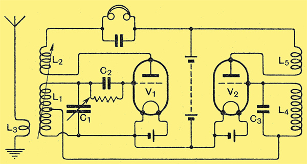
Fig. 1. - Fundamental arrangement for super-regeneration. V1 is the detector - amplifier and V2 the quenching oscillator.
There are various ways of obtaining this effect in practice but one only will be discussed here, and the form this takes is shown in Fig. 1. Briefly, its action is as follows: variation in the resistance of the receiving circuit L1, C1 is achieved by varying periodically the potential on the grid of the valve V1 by means of a low frequency oscillating circuit L4, C3. When the oscillating potential of the grid of V2 is positive, a conduction current flows from the tuned circuit, thus increasing its effective resistance. During the other half cycle, when the grid of V2 is negative, no conduction current flows; the circuit of L1, C1 thus having a very low resistance, which is determined by the regenerative effect produced by the feed back, or reaction coil L2; It is during this period that signal currents flowing in the aerial circuit, coupled by the coil L3, build up, are rectified by the action of the grid detector V1 and become audible in the headphones.
Intermittent Cessation of Signals
The ear, being unable to respond to rapid changes, does not notice the intermittent cessation of signals at each half cycle of the oscillator V2, and in this respect resembles the human eye, the retentive effect of an image on the retina precluding any determination of change in form if the variations are sufficiently rapid. This defect, if it can be regarded as such, makes moving pictures possible, so likewise does the accommodation of the ear render super-regeneration possible. It has been suggested in some quarters that for the reception of broadcast matter and telephony signals the quenching oscillations generated by V2 should be above audibility, since obviously these will modulate the carrier wave and be superimposed on the signal. Recent experiments carried out by the present writer have shown, however, that the performance in general is better with a low quenching frequency, but practical considerations preclude the use of those much below 6 kHz, otherwise it cannot be filtered out after rectification without noticeable deterioration of the quality of reproduction.
Armed with these few fundamental facts it only remains now to consider how best we can apply the principle of super-regeneration to a practical case, for there are certain features inherent in the system that tend to impose a limit to the amplification desirable at the detector stage. If the maximum possible amplification is extracted, background noise is inclined to be rather troublesome. This is due to the exceptional sensitivity of the detector-amplifier, which not only responds to minute electrical pulsations having a tunable component, but greatly amplifies the inherent valve noises brought about by very small changes in the operating state of the valve. For example, fluctuations in the electron emission from the filament normally passing unnoticed become audible in this system, but even with the valve operating well below its maximum the amplification available is quite sufficient for all practical purposes. Under these conditions the background is then comparable with that present in any other arrangement affording an equivalent overall amplification.
Quenching Oscillations
Therefore, in the receiver with which the experimental work was undertaken there were two LF amplifiers after the detector which, with the separate quenching valve, gives four valves in all. Since general-purpose valves are now obtainable at a reasonable price, there is no point in unduly complicating the issue by endeavouring to make one valve serve two purposes, such as combining the functions of quenching oscillator and detector.
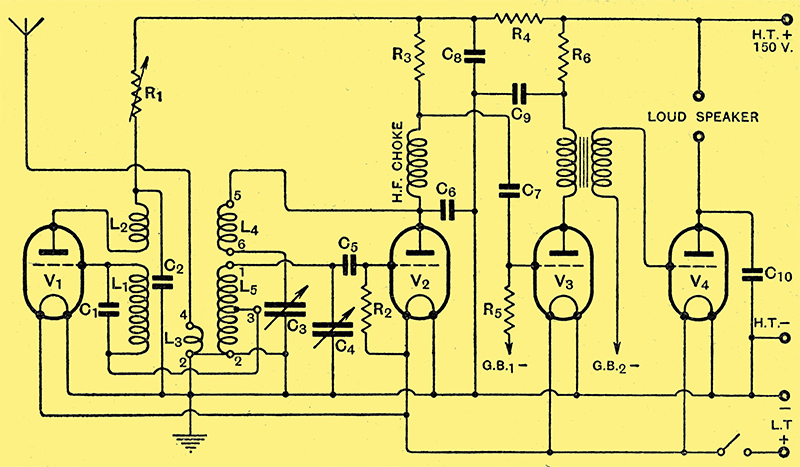
Fig. 2. - Theoretical circuit diagram of the Super-regenerative Four receiver for short waves. Values are as follows: C1, 0.05 μF; C2, C8 and C9, 2 μF ; C3, 0.0003 μF; C4, 0.00015 μF; C5 and C6, 0.0001 μF; C7, 0.01 μF; C10, 0.001 μF; R1, 0-2 MΩ variable; R2, 5 MΩ; R3, 30 kΩ; R4 20 kΩ; R5, 2 MΩ; R6, 10 kΩ; V1, V2 and V3, HL type valves ; V4, small power valve.
The theoretical circuit is shown in Fig. 2, from which it will be seen that, with the exception of the quenching oscillator V1, the circuit follows quite orthodox lines. Coils L1, L2, and capacitor C1 constitute the quenching circuit, the frequency of which is just within the audible range, and if the superimposed oscillations are found to be troublesome they can be suppressed by fitting a filter between the anode of V3 and the primary of the LF transformer. One of the Heterodyne Whistle Filters made by Postlethwaite Bros. will serve quite well for this purpose.
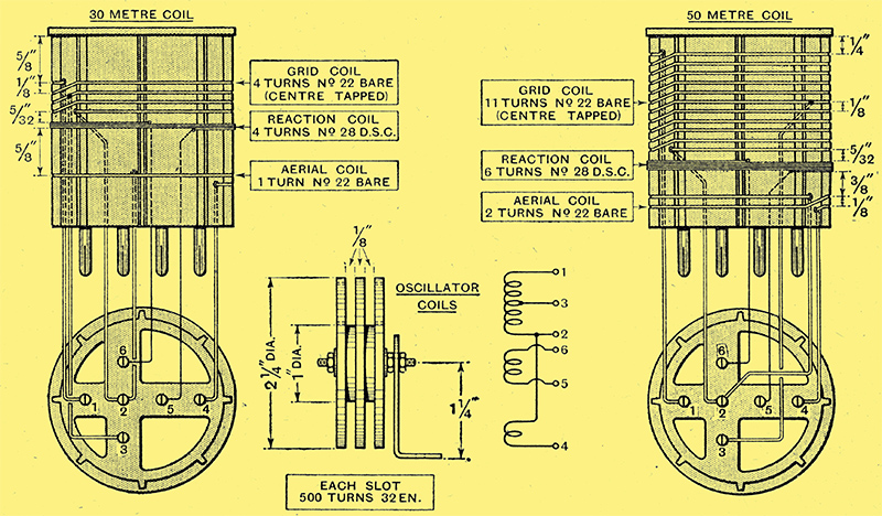
Fig. 3. - Details of coils and winding data, also dimensional drawing of wooden former for quenching oscillator coils.
Details of the small wooden former supporting coils L1 and L2 together with the winding data, are given in Fig. 3.
Oscillations generated by V1 are controlled by a variable resistance in series with the HT, since this is a more economical method than utilising a potentiometer arrangement, especially as the receiver was battery operated. This resistance (R1) is variable between 0-2 MΩ, and can be a Clarke's Atlas Universal Rheograd or a similar type, but of different make. It should be adjusted so that the valve just oscillates. Strong oscillations are not desirable, and if they are too weak adjustment of C3 to the point where the detector breaks into oscillation periodically suppresses the quenching oscillations and produces an effect akin to motor-boating. A fractional turn of R1 corrects this and gives a satisfactory working condition. The reaction capacitor is adjusted to give the best compromise between signal strength and background noise.
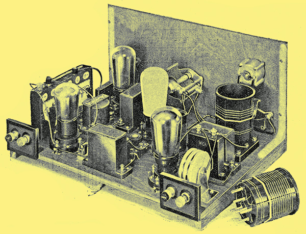
Rear view of receiver with valves and coil in position.
With R1 adjusted so that the quenching valve is inoperative, the set can be used as a straightforward Det. LF arrangement, in which condition CW signals are receivable in the normal manner. When a telephony station is heard, V1 can be brought into action and the super-regenerative properties utilised to boost the signal for loud speaker reproduction.
Under super-regenerative conditions more reaction capacity is required at C3, which, of course, is in keeping with the theory, since the circuit L5, C4 will not reach the critical state for self-oscillation until its effective resistance is reduced to a lower level.
It will be noticed that the tuned grid coil L5. is provided with a centre tap, to which point the grid return of the quenching circuit L1, C1, is joined. As one coil will not cover a sufficiently extensive waveband for normal purposes, and switching would be an undesirable complication, coils L3, L4, and L5 are wound on a six-pin former. Two coil units have been prepared, which, in conjunction with the 0.00015 μF capacitor C4, cover wavebands from 21 to 36.5 metres and 35.5 to 76.5 metres respectively. The tuning system must be modified for ultra-short wave reception, special coils and capacitors being essential.
So far as the disposition of the components is concerned, it will suffice to say that, provided the usual care is observed and that those constituting the tuned circuit are suitable for short-wave use, no special precautions seem necessary, and if the constructor desires to exercise his constructive ingenuity he is at liberty to do so within reason.
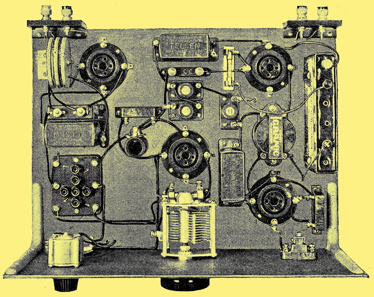
Plan view of Super-regenerative Four short-wave receiver with valves and coil removed and showing layout of the components. Filament and HT leads are run below the baseboard, and a four-way battery cable replaces terminals to preserve a neat appearance.
|