|
An Early Discovery
Truly the phrase, 'They come as a boon and a blessing to men', could be applied to the wireless valve. I have already mentioned in a previous chapter the historical data with regard to the discovery and improvement of the valve. There is a story current which impresses the details of the discovery upon one's memory, and which, although I will not vouch for its exact truth, is pleasant telling, and will, I hope, be pleasant reading.
On one occasion a man, who thought a little further and deeper than his fellows, was watching the electric-light globe within his laboratory. As he watched it the filament suddenly snapped and the light went out. You or I would, perhaps, have taken the globe out of its socket and inserted a new one, caring little or nothing for the broken globe which we would have consigned to the dust heap. He, however, observed other globes which were approaching the stage at which the filament became worn out and, remembering the fact that an electric current passing through a wire of high resistance causes heat, and from heat incandescence, and from incandescence light, he remembered, too, that from resistance within the filament of an electric-light globe should come a wearing-away process which would finally end in the fracture of the filament after it had become thinner and thinner with use.
When a wire of high resistance, and a very thin one at that, is placed within the vacuum of the globe, heat and incandescence are the result of the passage of an electric current through that filament. Whilst the electric-light globe was in use he noticed that a blackening process seemed to occur upon the inside of the glass of which the globe was made, and that, with the increase of blackness the approaching death of the lamp was foretold. He queried within his own mind as to the reason of the blackness upon the inside of the glass, and wondered whether that had any direct bearing upon the final fracture of the filament. He found that it was not dirt which caused the blackness, but a pitting of the inside of the glass as though it had been bombarded by some tiny particles travelling at a high velocity and burying themselves deep in the glass, the blackness being produced by the reflection and refraction of light from the pits in the surface of the glass. What, then, he queried, could be the cause of the bombardment within the electric-light globe, and what could be its connection with the wearing away of the filament? To find out something about this, he inserted. a piece of metal within the globe at the time that it was first made and, upon connecting this piece of metal to an outside circuit together with a battery, found that a flow of electricity was registered in that outside circuit connected to the piece of metal. At the same time the blackening of the inside of the glass decreased. In other words, he had discovered that, all the time that heating of the filament of the lamp took place (due to an electric current being passed through it) something was given off from the filament which could be caught up upon a piece of metal connected into a circuit in which the lamp was included. This metal anode, of course, is a good conductor of electricity, and he found that that something which had pitted the glass of the electric-light globe would produce an effect of a flow of electricity in a circuit in which the piece of metal and the valve filament were connected. (SeeHow I Invented the Thermionic Diode, The Origin Of the Valve and John Ambrose Fleming)
The Modern Valve
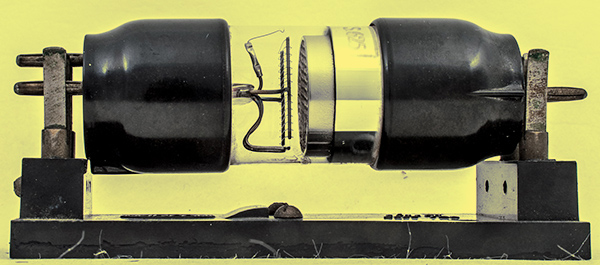
The new Marconi Screen Grid Valve S625.
To-day we call this flow from filament to the other piece of metal, called the plate of the valve, or the anode - an electron stream. This stream can only flow in one direction, that is from the filament to the plate of the valve. The grid of the valve, which has been inserted since the first experiments mentioned above, acts somewhat in the way that a policeman would act with a mob of people passing up a street. The grid controls, as the policeman does the crowd of people - sometimes encouraging and sometimes retarding - the flow of electrons from one place to another. It controls and regulates the flow of electrons from valve filament to valve anode or plate. The way in which this grid controls the flow of electrons is rather involved but, briefly, something of the following occurs: The grid of a valve is between the heated filament (sometimes heated to incandescence and sometimes not, as when dull emitter valves are used), and the piece of metal called the plate or anode. This grid has, if charged with electricity, the power to attract electrons from the heated filament or to repel them. It is the policeman, the electrons are people, and the road over which the people are crowding is from the filament whence they come to the plate or anode to which they are going. If the policeman says 'hurry along, please', then he gets the people through the road. quicker and increases the flow of people through the road. If he tells the people to 'keep back, please', then he repels them and 'holds up the traffic'. (See Lee De Forest)
Similarly, if the grid is charged with a positive (+) or negative (-) voltage it is enabled to attract or repel the flow of electrons from the filament to the plate. Unlikes, in magnetism and electricity, attract each other, and likes repel. Therefore, if that voltage affixed to the valve grid is not of the same type or polarity as that of the electrons being thrown off from the filament, the result will be a speeding-up of the flow. If the grid voltage, as supplied by a battery, is so connected that a repelling force is applied to the electron flow, then the flow will be reduced. In the more elaborate sets grid voltage is applied by means of what is called a potentiometer. This is nothing more nor less than a resistance through which voltage or pressure is applied. By means of a slider, upon the potentiometer variation from a positive to a negative value upon the grid of the valve is obtained. This all sounds rather technical, but if you will consider for a moment you will see how this action takes place within the valve. It has been found that the flow of electrons from the filament of the valve is a negative (-) flow, and we know that in electric circuits and, by the law of magnetism, any two poles that are alike repel each other, whilst two unlike poles attract. Your high-tension battery applies to the plate of the valve what is called a positive potential, or in other words, an inclination electrically to positive or + value. So that, you see, between the filament and the plate of the valve we have a sense of attraction and not of repulsion in that the electron flow from the filament of the valve is minus and the plate of the valve is plus. Because of this, the flow of the current supplied by your low-tension accumulator to the filament of the valve (in its process of heating that filament) enables the filament itself to throw off electrons from the atoms of which it is composed, into the vacuum of the valve. These are caught up upon the plate of the valve, being attracted to it by the positive charge supplied by the high-tension battery to the anode or plate.
You can, if you like, imagine the plate of the valve to be something which is sucking, from the filament, the electrons which the latter is giving off. This sucking process tends to increase the electron flow. The mere fact that the electron flow is in one direction only from the filament to the plate of the valve, enables the valve to act as a detector or rectifier. Here it is that we have the comparison with our old friend the crystal. You will remember that, when we were talking about the crystal, as used in a receiving set, we said that it allows current to pass through it in one direction only, by opposing, with a very high resistance, any flow of current in the reverse direction. In other words, both crystal and valve can be compared with a kind of mechanical one-way valve, if one is going to use a popular analogy.== A wireless valve, therefore, can be first of all a detector. Hence, the name of detector is given to one of the valve positions or stages within a receiving set. The flow of electrons to the plate of the valve is increased, up to a certain limit, by the grid voltage, and by, within certain limits only, the amount of high-tension voltage applied to the plate or anode. The point at which the electron flow ceases to be further increased, is called saturation point. This point is reached when a complicated state of affairs within the valve develops. It is unnecessary to mention here the detail of exactly what occurs within the vacuum of the valve and between the electrons as they are rushing over from filament to plate. The books mentioned at the end of this chapter deal more fully with this matter.
Care of Valves
Too much high-tension current destroys the efficiency of the valve and, to put it technically, impairs its emission. In other words, the flow of the electrons through the valve is upset. This may possibly result in overheating the plate of the valve which would, in turn, result in gases being given off into the vacuum of the valve, due to that overheating. Thus, softening of the vacuum takes place, and its efficiency is impaired. It would be folly to apply more high-tension current to any valve than is stipulated by the manufacturer of that valve. This is stipulated very clearly by him upon the box containing the valve at the time that it is purchased. You will also notice that a particular filament voltage is stipulated. Sometimes a valve requires 1.8 Volts to heat the filament. In such a case it will be necessary to use a 2 Volt accumulator without resistance or rheostat and not a 4 or 6 Volt. Similarly, other valves require the use of a 6 or 4 Volt accumulator, and less voltage than that stipulated applied to the filament would not produce the required results. Keep, always, to the manufacturer's instructions.
Frequently the contact made by the legs of the valve to the holder into which they fit is not a good one, and it would be well, occasionally, to open up the legs by means of the split metal of which they are made. Do this very carefully and see that a tight connection is produced. A loose connection will often produce crackling noises in reception. Keep your valves free from mechanical strain. Do not allow them to be knocked in any way, nor to be liable to any jar or vibration unless you take precautions to see that they are protected. Valves are expensive things, and it pays to look after them.
I give below a list of books which deal more deeply with the theory of the valve, to which those who are sufficiently interested to go further into the subject may refer.
- R D Bangay, The Oscillation Valve, Iliffe & Sons, Ltd.
- The Admiralty Handbook of Wireless Telegraphy, H M Stationery Office
- Dowsett, Wireless Telephony and Broadcasting, Gresham Publishing Co., Ltd.
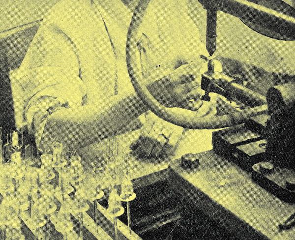
The Foot
Stem Making: The operator is fitting the parts in position for fusing together. Note the blowpipe flames on the left of the picture.
I was fortunate in being able to see valves being made by one of the companies who make large numbers of them - possibly you are using some of those very valves now. First of all, at the bottom of your valve, you have what is called the foot of the valve. This, in the particular type of valve which I saw being made, was of glass. It is that little glass tube which holds the supports for the parts inside the bulb of the valve, which are called the plate, the filament, and the grid. Let me describe it to you exactly as I saw it.
A girl was at a machine, cutting off sections of a long glass tube, each section was to become the foot of a valve. Then the little glass sections were passed in a box to another girl who put them into what is called the 'dolly' (jig). This dolly is really an iron arrangement with a hole in the centre, which holds the little piece of glass tubing. All the time that it holds it, it turns round and round. The dolly is mounted on a circular machine which also has five other dollies mounted on it in the same way, and they all turn round, each one having a piece of glass tubing fixed to it. As the machine works electrically, the dollies are put first of all into a gas flame of a certain heat, which softens the top of the little glass tube. Then the machine turns, and a hotter gas flame softens the glass still further, and so on until a little finger made of steel comes down and presses on to the revolving piece of softened glass in its dolly and turns the glass edge of the tube over, making what is called a flange. This is the flange which, later on, fits into the bottom of the glass end of the valve. Then I saw a really wonderful process called welding, where short lengths of copper wire are welded onto pieces of platinum and on to little metal supports which will later hold the three essentials of the valve - the filament, the plate, and the grid. This welding process is carried out in what is called a non-oxidizing flame, so that no insulating substance can be formed upon the wires in the process. If any were formed, a great deal of the correct working of the valve would be impaired.
Different sized pieces of platinum are welded for the grid, the anode, and the filament. Girls do this, and it is very delicate work, because each little piece of wire is very, very small. The next process is the fixing of these welded wires and supports to the glass foot of the valve. Another machine, like the first, With five dollies, is used for this. First of all, the little glass foot of the valve is fixed into a dolly and a girl lays the copper wires, which are later to form the contact to the legs of the valve, upon the foot. Then the dollies turn round and round and pass through gas flames which get hotter and hotter, until the glass is soft, this time at the centre of its length and not at the end. When it is soft, two little hammers come up and bang together with the soft glass between them. When they bang together the soft glass is in this way moulded tightly around the copper wires. The foot of the valve, with the copper wires fixed to it, is then put into what is called an annealer. This is really an oven with a revolving stand fixed to it. The stand holds the glass foot of the valve with its wires fixed to it. which is still very hot and quite soft. If the glass were to cool down very quickly in the cold air it would crack. The annealer prevents this and passes the glass slowly through the different temperatures of the oven until it has gradually cooled down. The annealer is made of copper because copper cools slowly. The foot, as it is now, has four copper wires sticking out of the bottom of it and above it the four supports of the electrodes. If the valve maker were then to make the valve without examining the foot, what is called strain might occur where the glass has been squeezed together around the wires, and a crack might possibly result which would cause a short circuit in the foot of the valve when used in your set. The foot, then, has to be examined, and this is the way in which it is done. What is called a strain viewer is used. This looks like a large box with a little telescope sticking out of one end of it. An electric lamp is at the other end, which sends its light into mirrors at different angles. These rays of light are thrown into the eyepiece of the little telescope. When you look into this telescope you see a mauve coloured light. The foot of the valve is put into the box in the line of sight of the eyepiece. If the glass, in being squeezed around the copper wires, has been strained, then all sorts of colours show in the glass. If no strain exists, then only one colour appears. If strain is found, then back the valve foot goes into the annealing oven. Again, the glass is heated to red heat and then carefully and gradually cooled down. This takes away the strain. The light used in this strain viewer is called polarized light.
The Electrodes
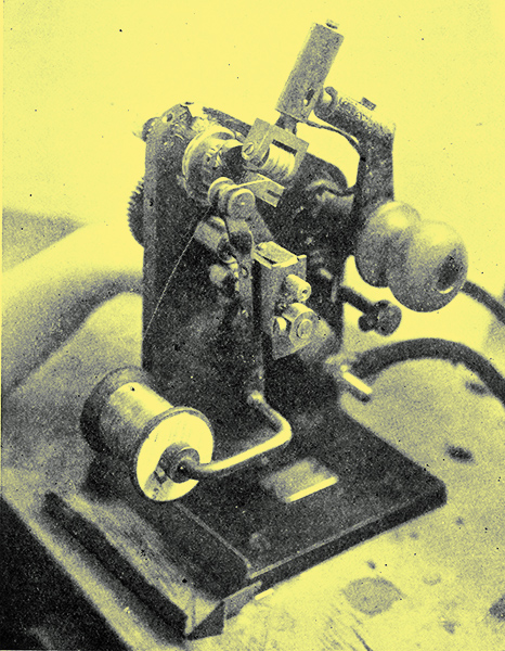
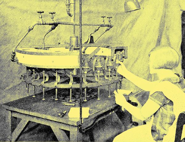
Grid Winding Machine: The grid is partly wound on the flat former and the welding roller can be clearly seen in position.
Let us leave the making of the foot of the valve for a moment and talk about the making of the various electrodes, as they are called - the grid, the plate, and the filament. There are two sorts of filaments to valves. One is the dull emitter type of filament and the other the bright emitter. The dull emitter was the first that I saw being made. A coil of very fine wire, as fine as a hair, is passed through a little holder on to a little machine whose action was very much like the action of a rifle. In front of this machine was a tiny arm which regulated the length of each piece of wire passing into the machine. Then, suddenly, there was a click as a strong catch was released, and a striker in the machine hit the thin thread of wire, fixing to it a tiny V shaped piece of metal. This process is called tabbing. These tabs are fixed so that the filament can be easily attached to its supports on the foot of the valve. The filament wire is cut by the help of a gauge, into its correct length, then carefully examined by an examiner with another gauge. So that these tiny pieces of wire with the tabs attached may not be lost, they all have to be carefully mounted in trays for fixing at a later date to the filament supports. The bright emitter filaments are just cut out to their proper lengths and are ready for fixing Without any tabs being affixed to the filament supports.
The making of the grid of a valve is an interesting process. The wire of which the grid is to be made is formed into a spiral for the spiral-shaped filaments, and later is mounted on the support upon the foot of the valve, by electric welding. The spiral is made in a continuous length and then cut into its correct lengths later on. Another type of grid is wound by hand. A pitch is used for this, which gives the exact distance between each band of the wires in the grid. When this winding is done by machinery the pitch is, of course, unnecessary, because a machine can work so much more accurately than the human hand. The making of the plate or anode of the valve is simple. It is cut out, the edges are turned over, and then it is welded to its supports by the electric process.
The making of the foot of the valve and of the plate, grid, and filament, was most interesting and has a most important part to play in the function of the valve which, in turn, is essential to reception where valve receivers or valve amplifiers are used.All these odd parts have to be assembled, and this is how it is done.
The foot of the valve, with its supports. has to be attended to first. The supports themselves have to be bent into correct positions to take the parts to be fixed to them. You may have noticed that in various types of valves the filament, grid, and plate, are in different positions. The position of the electrodes just depends on the type of valve which is being made. To fix these the supports for the electrodes have to be bent. A very wonderful machine is used for this. First of all the foot of the valve, with its supports, is put into the front of the machine, a stamp comes down and bends the support wires to the required position. Down a little shoot and out of the machine comes the valve foot. This shoot is just like those used for underground-railway ticket machines. A girl examines the valve foot and passes it into another machine which simply deals with the two filament supports, and flattens the ends of them, or bends them so that the filaments may easily be held. Then another machine takes that valve foot and also the length of filament wire (which I have already described as being cut up and tabbed), and fixes it to the filament supports. The next journey which the plate of the valve makes is to another bench where a girl attaches the grid of the valve to its support by electric welding, and the plate of the valve to its support in the same way. The little machine which does this welding looks very much like a tiny vice, the two sides of the vice are the two poles of the magnet round which a current of electricity is passed. A spark jumps across the gap between the two parts of the vice-like instrument, and as it jumps, melts a tiny portion of metal of the support which very quickly becomes solid again, holding the anode to the piece of metal which forms its support. With very special types of receiving valves the plate and grid have to be adjusted for fixing before they are actually welded. For this, special examiners with tiny instruments adjust the exact distance between the three parts of the valve and then pass them to the welder. This examiner makes quite sure that the length of the filament and the disposition of grid and plate are correct.
Welding Electrodes: A tray of stems ready for mounting anodes is on the left.
The Glass Bulb
The next step in the making of the valve is the making of the bulb. The glass bulbs go into the valve works looking very much like empty electric-light bulbs, open at the narrow end. A girl takes a bulb, and, twisting it quickly in her fingers, puts the closed end of the bulb into a hot gas flame. This softens the glass at the centre and top of the bulb. With her other hand she takes a thin glass tube, and softening this too, sticks the thin tube on to the top of the softened bulb, pulling it out a little to make a tiny hole where the two meet, and turns it quickly with both hands all the time that it is cooling down in the air. The bulb now appears just like a diver's helmet with the air tube fixed to its top. You could easily blow down the thin glass tube into the bulb. The bulb then goes to another instrument with dollies similar to the one which I have described as being used for the making of the glass foot of the valve. The bulb is put into a dolly, and passes into a flame which cuts off the unwanted piece of glass at the bottom of the bulb, making the whole bulb of the correct length for the valve which it is to be. As the dollies revolve and pass through hotter and hotter gas flames, a steel instrument opens out the softened glass at the foot of the bulb to the correct distance to take the flange of the valve foot. Another machine with dollies takes the bulb and also the foot of the valve, with its grid, plate, and filament attached to it, and with the four wires, which run to the supports of the electrodes, fixes it into the bulb. The glass is joined together after being softened by hot gas flames. After coming out of this machine we have our valve looking just as your valve does now, except that it has attached to the top of it this funny glass tube and, of course, it has not yet any filament legs or any marking. When it leaves the gas flame it has to go through an annealing oven, which allows it to cool gradually to avoid strain and possible breakage of the glass.
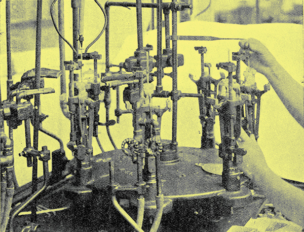
Drawing Out the Air
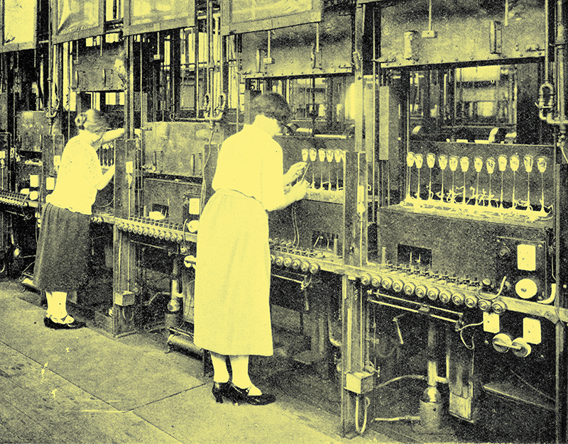
Exhausting Bench: The baking oven is seen at the top of each bench. In front are the switches and resistances for lighting the valve filaments during exhaustion.
The next step is pumping. For this the valve is turned upside down and the thin glass tube sticking to its top is attached to a similar tube on the pumping machine by softening the glass by heating.The pumps are set to work and all the air and gases are sucked out of the valve. Whilst pumping is going on, a cover is drawn over the valve, and it is really then in a type of oven which is heated to about 400° Centigrade. This drives gas out of the actual glass of the bulb, and the pump sucks the gases out of the bulb itself as fast as the heated glass gives them out. The valve then gradually cools down. Whilst pumping is still going on, the four small wires from the foot of the valve are connected to electric circuits which pass a current through the electrodes. The filament is heated by this means almost to melting point in order to free gases from the metal of which the filament is composed. The plate of the valve is heated until it is bright red, and is also subjected to what is known as electron bombardment from the filament. This frees gas from the plate as well as from the filament, and the pump sucks the gases away whilst this is happening.
The number of volts to which the plate of the valve is subjected varies between 300 and 2,000, dependent upon the type of valve being constructed. The voltage applied to the filament of the valve is low, by comparison, and yet is slightly higher than the voltage which will ordinarily be used when the valve is sold and used on the receiving set. This applied voltage is connected for about 30 minutes, pumping taking place all the time. Then the current is cut off and the bulb of the valve is heated at the point where the thin glass tube has been connected to it. Our valve has now been sealed at both ends and exhausted of air and of gas. The glass and the metal of the electrodes have been made to give out any gases which they may contain, and these gases have been taken from the valve. All of this can only occur to bright emitter types of valves.
Capping: The valve is held in the clamps shown and passed slowly through the gas oven to bake the cement hard.
With dull emitters the process is the same up to and including the freeing of the gases from the glass of the valve by baking it at 400° Centigrade. The valve is then sealed off in the manner which I have just described, and is passed to what is called the eddy current bench. We still have, in the case of dull emitter valves, the freeing of the anode from gases. This is done by heating the anode by means of what is called an eddy current. There is magnesium in the anode of the dull emitter valve, and the eddy current process causes the magnesium to be volatilized. When this takes place the gas given off by the plate of the valve is sucked up and is taken on to the inside of the glass walls of the valve, and is kept there by the volatilized magnesium. This gives to the dull emitter type of valve, which is treated in this way, the silvered appearance which you all know so well. Both types of valves are then carefully examined and tested. When this is done those valves which stand the test are capped. There are two parts to the cap of the valve - the shell and the insulator. The cap is pasted on to the base of the shell. The insulator is fixed into position in the shell, and the four copper wires, which you remember were fixed to the foot of the valve, are threaded between the valve legs, which you will notice are slit for this purpose. The wire is cut off and soldered to the leg of the valve to which it applies, two of the leads going to the two filament legs, one to the plate leg, and one to the grid leg. Then the shell of the valve is pinched by means of a hand machine on to the insulator, and the cap is fixed by this means.
Finishing Touches
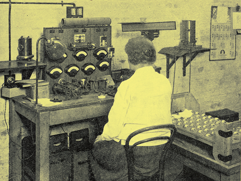
Testing Valves: Every valve must pass at least five tests on this board.
After cleaning and dusting for the valve becomes very dirty going through so many hands in this way - a final test is made with instruments recording the emission, vacuum, and general behaviour of the valve. The glass is marked and stamped with the various markings necessary to it, and the valve is ready for issue for use by you or your receiving set. It has taken a long time to describe all this, but yet the process of valve making, from beginning to end, though so complex, is rapidly carried through to ensure a maximum output within the minimum space of time necessary to efficiency.
After-Care of Valves
Just a word about the care of your valves, which may serve to give you longer valve life. If the makers say that the filament should be 3-5 do not use 6 Volts, because you think that, by doing so, you get rather louder signals. The volume of sound may be increased but you are throwing a very great strain upon the filament, and it will not be long before it gives way under it. Do not exceed the anode voltage as applied by the high-tension battery. Use just sufficient to give good results and no more. This applies particularly to high-frequency and rectifying valves. On the low-frequency side of the set, high voltages may often be used with advantage, but here again the maker's figures should not be exceeded.
Do not bring your filament suddenly under full load by switching on the low-tension current; always bring the filament up to its proper heat gradually by the use of the filament resistance.
The practice of switching in the filament before the high-tension is an additional safeguard against filament burn-out by the accidental interchange of filament and HT leads.
Be particularly careful of your low-temperature filament (dull-emitter) valves. Overheating their filaments may not result in actual burning out, but it will lead, very likely, to the destruction of their low-temperature qualities.
Remember that valves are delicate pieces of apparatus. They will stand a reasonable amount of ordinary wear and tear, but they are not intended to be roughly handled. Never leave your valves lying about on the wireless table, but always place those which are not in use in their boxes, and see that they are kept where they are not liable to receive jolts and jars.
Useful Calculations
Upon each valve specification as given in the valve box the terms impedance and amplification factor occur. The first is an expression used to denote the internal resistance of the valve concerned. It is the object of all concerned to increase the amplification factor (usually expressed as μ) and to decrease the impedance (expressed Ra) as far as possible. In other words, the ratio of Rato μ should be as high as possible = μ / Ra . An approximate calculation of the amount of grid voltage required for a known anode (or plate) voltage as applied to a valve may be made by the use of the formula:-
Anode volts (EA) / Twice the amplification factor (2 μ)
All photographs courtesy Edison Swan Electric Co Ltd.
|