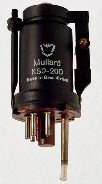
This exhibit is new and came in a moulded polythene box. This Klystron was designed for microwave RF generation of about 20 mW at 9-10 GHz for use as a local oscillator. It produces a continuous output and can be modulated for communications use. The output power is taken from the probe by passing the tip into waveguide. The base for this valve is special but an International Octal holder with pin four drilled out is equivalent.
In operation the electrons pass from the cathode through the resonator and some pass on to the negatively charged reflector. The reflector voltage is arranged so that the velocities of the electrons reflected back into the resonator will set up oscillations. The resonator cavity is mechanically tuned and at the correct voltages RF is produced at the probe. The voltages are adjusted for maximum output. Klystron frequency will change rapidly for small changes of voltage or temperature. Thus these devices are required to operate from stabilised supplies and be isolated from temperature fluctuations.
To obtain frequency modulation is simple, a small modulating voltage is superimposed on the DC of the reflector.
Typical operating voltages are: cathode grounded, resonator at +300 V at 25 mA, and reflector at -100 to -200 V at 5 μA. The klystron produces RF with the mechanical tuning and reflector voltage at quite critical points. Several RF producing conditions existing for a particular valve. The strongest being the one chosen.
The probe is 31 mm long and metal cased for 23 mm. The mechanical adjustment (shown on the right) acts on a pair of steel strips that are moved apart by the screw action. This movement is passed to the top of the valve where corrugations in the envelope allow a small change in the internal cavity size.
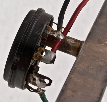
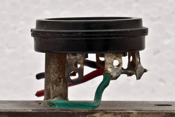
The special base attached to WG16.
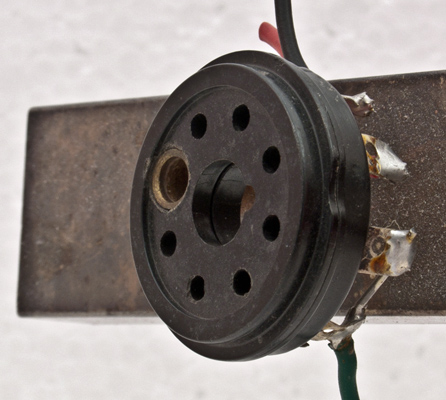
The base top view. This is an IO base with the probe passing through the tube attached to the location of pin 4.
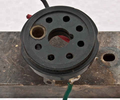
The base on WG16.
The probe tube is soldered onto the waveguide.
The thin metal tube envelope is 25 mm in diameter and, excluding the IO base pins, is 56 mm tall.