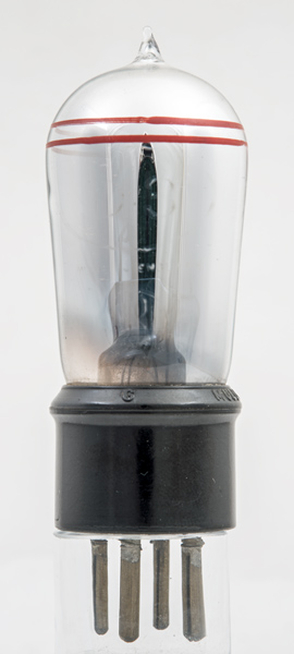
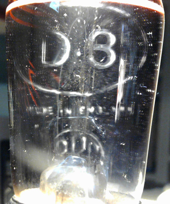
The D.3 design from Mullard dates from 1924 and was a replacement for the bright emitter HF. The D.3 is a thoriated tungsten dull emitter triode and the two red rings denote the HF variant. Other variants included one with two green rings for LF use also introduced in 1924 and the detector with two white rings introduced in 1925.
The D.3 HF had a μ of 17.
The D.3 differs from the D.06 in that the latter was designed with a 3.0 V 60 mA oxide coated filament whereas the D.3 range have thoriated tungsten filaments. Electrically they have the same characteristics.
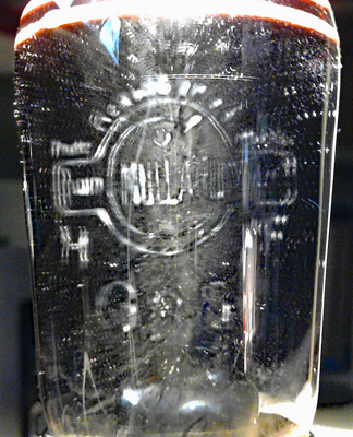
The reverse with the Mullard logo.
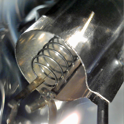
The getter coating is translucent in this valve and the anode can be seen to be mounted at 30 degrees to the vertical.
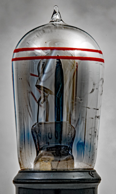
Enhanced version of the above image.
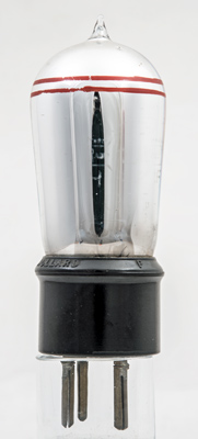
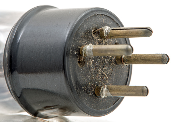
The base pins on all the D.3 versions are simple split pins with the lead-out wires soldered to the tops of the pins.
Trying to get a better image of the etched lettering.
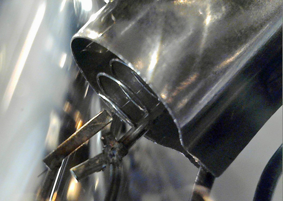
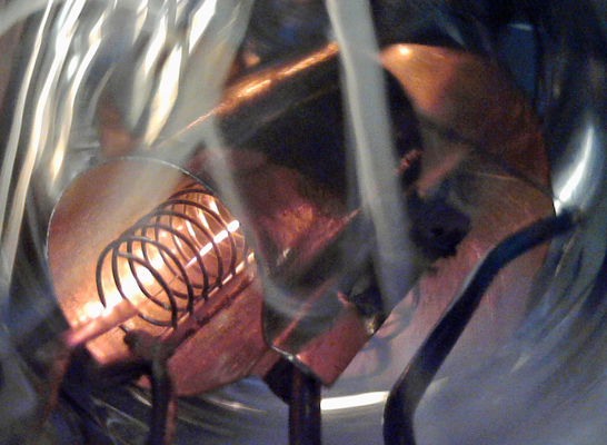
The base of the anode showing the geometry, helical grid and single strand filament.
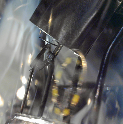
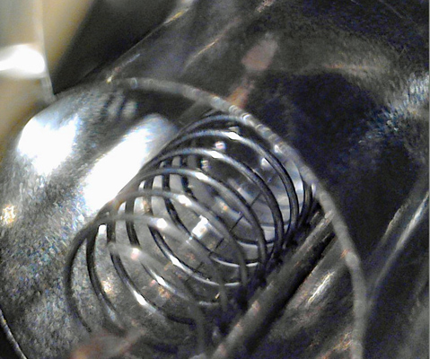
In this image taken with the microscope the detail of the folded anode, welded grid support and clamped filament wire can be seen.
A very clear image of the construction technique. Each loop of the grid is individually fixed to the support.
The filament wire is much thinner than the grid or the thickness of the anode sheet.
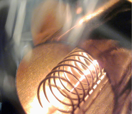
The thoriated filament running hot.
With the extra light from the filament the length of the anode can be seen together with the tension spring for the top of the filament. The spring can be seen to be fixed to a much thicker side support.
Reducing the filament current shows the cooler support end.
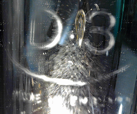
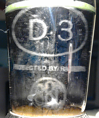
The main identification illuminated with a dark-field. The third BBC stamp can be seen.
The reverse etched lettering of the Mullard logo. The double image is caused by the reflection from the silvered inner surface of the glass.
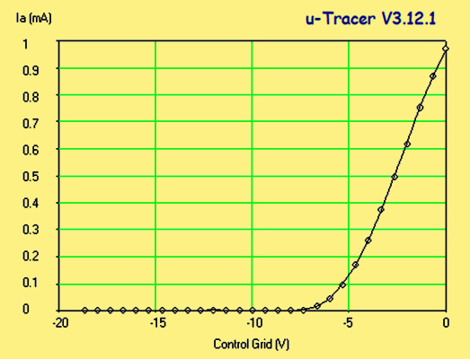
A μ-Tracer plot of the characteristic curve. The anode voltage is 100 V.
Special thanks to John Barber for allowing the museum to borrow his D.3 set.
The balloon envelope is 35 mm in diameter and, excluding the B4 base pins, is 85 mm tall.
Reference: 1003. Type D.3 was first introduced in 1924. See also1924 adverts.