The PY800 was one of the last rectifiers of its type to be developed and is based on the PY81 from 1952. This exhibit is from a pre-production run and is labelled as a sample.
It was specifically built as an efficiency diode for television line scan in sets using 110° deflection angle tubes. Considerable energy is fed to the line deflection coils and this has to dissipate during flyback. The efficiency diode channels this energy back to the supply rail smoothing capacitors for use on the next line scan.
The rectifier is specified as having a peak inverse voltage rating of 5,750 Volts, and a peak current rating of 450 mA. For sine wave use an input voltage of 1,500 Volts at 175 mA could be rectified. No voltage drop is quoted so the dissipation can not be given.
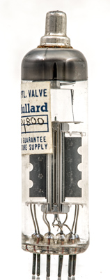
The ends of the nickel anode are turned out so that the bright inner surface is visible.
The stitched anode. In the centre is the cathode with the connection taken to the top cap. Very good heater/cathode insulation is required and looking at the image the method achieving this is apparent. Two rods like grid supports hold the insulated heater between them and a fine wire helix binds the heater and rods into single assembly that is then inserted into the wide cathode tube. Production models used an insulated wire helix to wrap the heather. SeePY800.
The thin glass tube envelope is 20 mm in diameter and, excluding the B9A base pins, is 72 mm tall.
References: Data-sheet & 1040. Type PY800 was first introduced in 1961. See also1961 adverts.