|
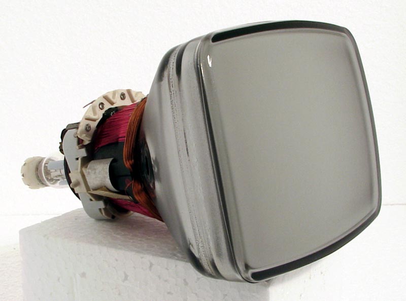
A small television picture tube type M14-170W.
Introduction
Since the original notes on 'Valves and their Habits' appeared in Practical Television in February 1961 a new generation of enthusiasts has emerged. At the same time the industry has produced a new set of valves.
This revised version of the original article includes all of the valves previously listed, even if some of them are no longer in common use, together with information on the latest types. The fact that a valve is mentioned in the list does not necessarily mean that it is certain to go wrong, or for that matter that it will not develop symptoms far removed from those given below.
Double valves, particularly the triode pentodes, still appear to be the most troublesome. They are naturally more difficult to construct and, as the entire valve is discarded when one half breaks down, their chance of failing is consequently twice that of a 'single' type.
Their versatility can indeed be their own downfall, since equipment designers often use them in a variety of unusual circuits quite removed from their original purpose.
Emergency Replacements
From time to time 'emergency replacements' are mentioned in the text. These are valves with the same basing (base type and pin connections), usually the same heater current, and only slightly different characteristics. You will not find them given as equivalents in valve characteristic manuals but they have proved themselves capable of keeping receivers going at such critical times when new valves of the correct type are not available.
BY100
Perversely enough our valve list begins with a diode. The BY100 silicon diode is to be universally found in modern dual-standard sets. Due to its size and price it may be used with advantage to replace the HT rectifier in earlier receivers. Its main disadvantage is that it is too efficient and, if insufficient care is taken to absorb the switching-on surge, damage can result to the electrolytic capacitors and the on/off switch. The HT line may rise in excess of the specified voltage and a limiting resistor should be incorporated to absorb the excess.
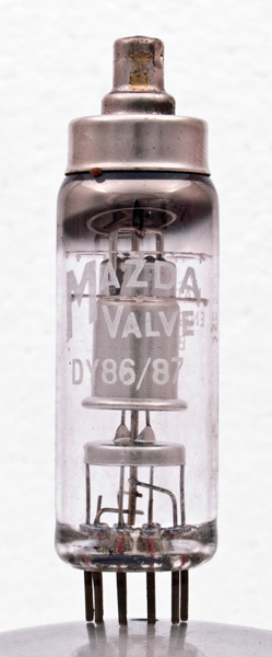
These two 1.4 V EHT rectifiers have similar characteristics to the EY86. Their heater wattage is the same as the U26, for which they make an emergency replacement with shortened life. The only difference between the DY86 and the DY87 is a silicone treated glass envelope on the latter for better insulation in humid conditions.
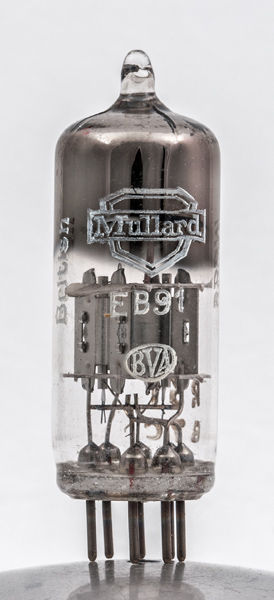
This sturdy little 6.3 V 0.3 A double diode has been used in detector, limiter, discriminator, and interlace circuits right from the beginning of post-war TV.
It has the habit of lighting up very brightly on switch-on, but this does not affect its performance. The commonest fault is heater-cathode leakage, causing hum in varying degrees. This may sometimes be cured in, series heater circuits by removing the beater to the low potential end of the chain.
An alternative is to construct a 'cold' EB91 using two OA71, crystal diodes on a seven-pin adaptor plug. Unequal halves only appear to affect line flywheel discriminator circuits of the balanced type and a simple check is to short the input anode and cathode together.
If the line whistle appreciably alters in pitch the valve is conducting unequally and should be replaced.
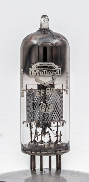
EBF80. EBF89
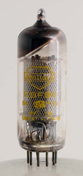 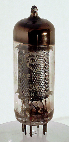
Two, 300 mA double diode pentodes frequently encountered in IF stages. Main fault is intermittence, usually stimulated by a gentle tap. Both have the same base connections and are interchangeable in an emergency, although the EBF80 is straight and the EBF89 is variable μ.
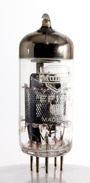
EF91, (6F12, 8D3, Z77, 6AM6)
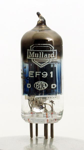 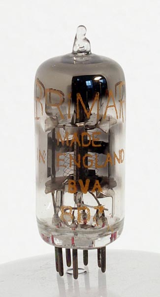 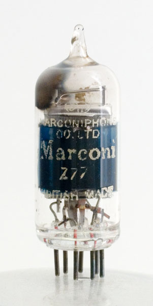 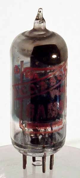 
This is a good reliable valve used in almost all early TVs but nowadays superseded by the EF80 or similar valves. As an RF amplifier it works well. Also as a mixer or IF amplifier it is efficient (even if it reads 'low' on test) but tends to give trouble if it is fitted into the video amplifier or sound output stages where it is being run pretty hard. The symptoms of low emission in the video amplifier stage are similar to a failing CRT.
ECC81 (12AT7, B309)
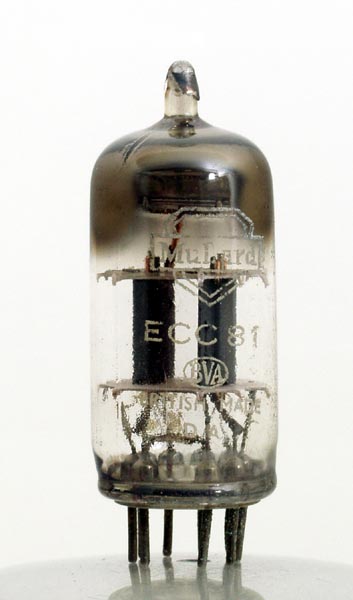 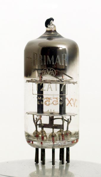
This valve is a medium impedance double triode employed as a frequency changer in five-channel receivers. The oscillator section usually ceases to function first, although the heater remains intact.
ECC82 (12AU7, B329)
 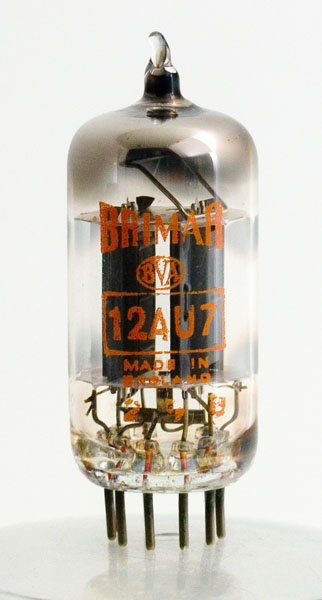
A double triode valve of low impedance with many applications such as frame and line multi-vibrators, AGC circuits, and driver stages in amplifiers. They prove, most troublesome in multi-vibrator stages, the symptoms being variation of the line (or frame) speed when tapped or the time-base running fast and difficulty of bringing into lock by the hold control.
It also contributes to the variable contrast when it is faulty in the AGC gating stages where one half is sometimes strapped as a diode. If only this section is faulty then an OA71 crystal can be tried as a substitute to save replacing the valve.
ECC83. (12AX7, B339)
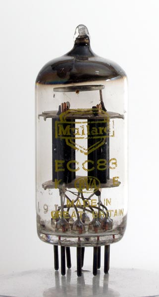 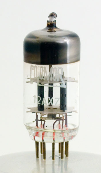
The third valve in the trio of double triodes is high impedance and, although normally encountered in audio equipment, is frequently used in discriminator stages of line time-bases. If you can only carry one of these three double triodes in the tool kit make it an ECC82.
Note
Tapped heaters are used on the above three valves (ECC81/82/83). In 0.15 A circuits connect to pins 4 and 5) in 0.3 A circuits join pins 4 and 5 and connect to their junction and pin 9. In the latter case one half of the heater sometimes blows prematurely, the symptoms being that the remainder of the chain is still lit but the other half of the faulty valve lights up much brighter than the rest.
ECC84. (6CW7)
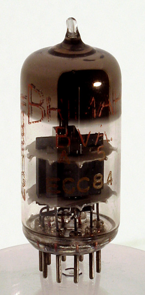
This is the 6.3 V, parallel heater version of the PCC84 cascode RF amplifier (See PCC84).
ECF80. (6BL8)

This is the 6.3 V parallel heater version of the PCF80 triode pentode (See PCF80).
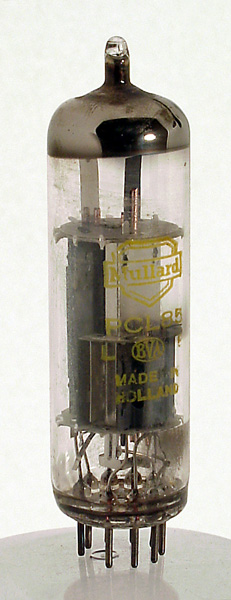
ECL80. (6AB8, LN152, 63TP)
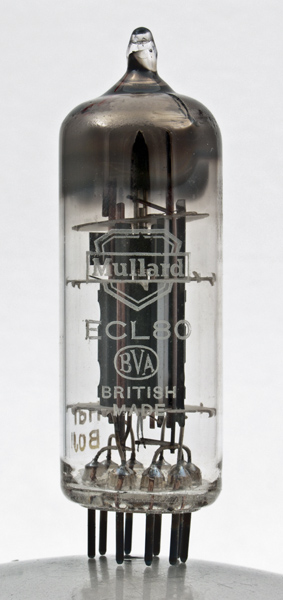
One of the earliest triode output pentodes (6.3 V 0.3 A), the ECL80 (6AB8, LN152), has a medium impedance triode and an output pentode capable of 1.4 W output (class A). Despite both sections having a common cathode this versatile valve is used as line and frame multi-vibrator, frame and sound output, frequency changer, etc.
A favourite combination is to use a pair, coupling their triodes as frame multi-vibrator and using the pentodes as sync separator and frame output.
Common fault symptoms with ECL80 valves
Line multi-vibrator: the line speed varies when tapped. Line frequency is too high to be brought into lock with the hold control. Watery verticals. Frame multi-vibrator: the hold control needs constantly readjusting, the speed varies if tapped, the picture 'judders' vertically. Frame output: lack of height, fold over at the, bottom of the raster.
Sound output: Distortion and self-oscillation (but check the cathode bias decoupling capacitor first). Mixer/local oscillator: the slow-heating triode section causes the sound and picture to arrive with a 'bang' after the rest of the set has warmed up. Coincidence detector (flywheel sync): produces oscillating verticals-picture waves about snake fashion.
Shortcuts
The sound output and sync separator stages are the least troublesome as far as these valves are concerned and the ECL80s in these two stages may sometimes be successfully changed over with those in the more sensitive parts of the set.
In series heater circuits a PCL83 can be used as an emergency replacement provided that valve holder pins 3 and 7 are joined, as they usually are.
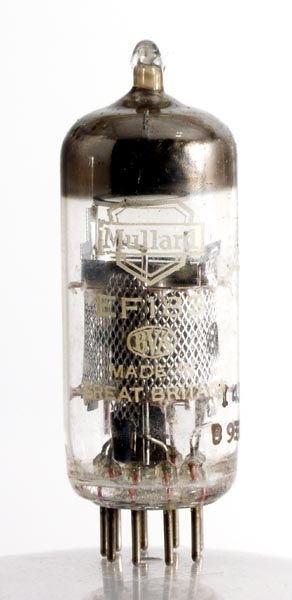
EF80. (64SPT, 6BX6, Z152)
Another reliable valve which will give good results in IF stages even after many years use. Although the characteristics are the same the internal appearance of EF80s may vary considerably. A bright spot appearing near the top or bottom of the electrode assembly sometimes denotes inter-electrode shorts.
In series heater circuits this valve can be used as an emergency replacement for 30F5, EF85, 6F19, 6F23. The pin connections are the same even though the characteristics are slightly different.
EF85. (6BY7, 6F19, 6F26, W719)
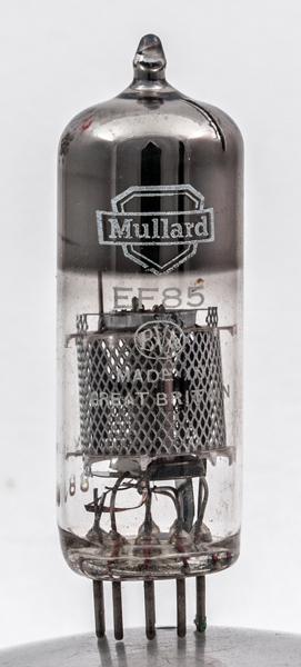
The variable μ companion to the EF80, this valve is commonly used as the first vision or common IF stage. Being variable μ its gain can be controlled over a wide range by the vision AGC line and, if the circuit is carefully arranged, the AGC voltage can also vary the grid to cathode capacity. In this way the input circuit tuning can be varied according to the signal strength so that the overall response is peaked towards the vision carrier on a weak signal and is progressively flattened to give a wide passband on a strong one. This arrangement 'automatic bandwidth control' has been in use for some years on one make of receiver.
A common fault is grid emission or inter-electrode leakage. This results in a positive voltage being fed to the AGC line and produces negative pictures.
EF183. (6EH7, 6F29), EFI84. (6EJ7, 6F30)
The two frame grid successors to the EF85 and EF80, giving double the gain with good design. The EF183 is variable μ and the EF184 is straight. The basing remains the same as the EF80, which you can use as an emergency replacement, but you will notice the difference. Well made valves, giving little trouble.
EH90. (6CS6)
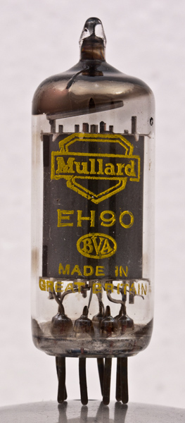
Seven-pin heptode found in the audio stages of dual-standard sets where it serves as locked oscillator detector on 625/FM and AF amplifier on 405/AM.
EL81. (6CJ6)
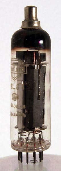
6.3 V equivalent of the PL81 used in parallel heater circuits (See PL81).
EY51
A wire-ended EHT rectifier with a 6.3 V 90 mA heater which is normally fed from a well-insulated winding on the line output transformer. This is the original EHT rectifier, which in 1948 made the AC/DC technique possible in the television set and which is still in extensive use today. During the years its peak inverse voltage rating has been raised to 17 kV in order to cope with larger tubes and higher final anode potentials and its physical size has been slightly reduced.
General symptoms of its failure are blackening around the glass just below the bell and a picture, which 'blows up' in size as the brightness control, is advanced (the latter fault may also be due to a displaced ion trap magnet). The high voltages present when running make the valve difficult to check by conventional means and the filament colour provides a useful means of ascertaining the operating conditions by comparing it against the filament colour of a similar valve run from a 6 V battery.
In many cases a dim filament will indicate a low-line output stage and it is not always appreciated that unless the line output stage is working correctly the EY51 may not light up at all.
An EHT short or excessive current drain by the CRT will also dim the filament and this property is useful to enable the brightness control to be set to a working level before adjusting the ion trap magnet when a new tube is fitted. The author found that if the brightness control is set to just cause the valve filament to dim slightly a bright raster is ensured when the ion trap passes its correct position.
If the filament is too bright, short life usually results, and this may be overcome by fitting a small resistor in series with the heater lead to absorb some of the surplus. A 22 Ω or 27 Ω carbon resistor, 0.25 W, is usually adequate.
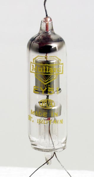
EY86. (6S2)
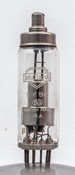
The EY86 is the plug-in version of the EY51 and has a slightly higher filament current and higher Peak Inverse Voltage rating. These improvements make for easier servicing and better results with the wider angled tubes.
The fault symptoms and general notes on the EY51 apply equally to the EY86. Early productions of EY86 valve had no apparent gettering (the metallic patch on the glass being absent) but current EY86 valves are gettered in the conventional way.
In a certain make of receiver the EY86 suffers a short life and if continual replacements are required a special replacement type TY86 should be used.
EL38
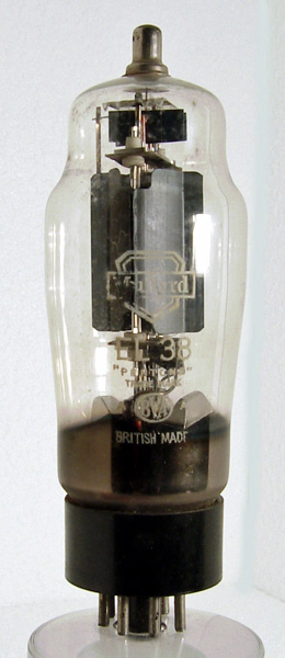
This is a 6.3 V octal based line output valve with similar characteristics to the PL38.
OA70, OA71
Two devices which if carried in a tool kit will cover most applications likely to be encountered. The OA70 will replace any vision or sound detector diode and the OA7l will replace most limiter or AGC diodes.
PC86. (4CM4)
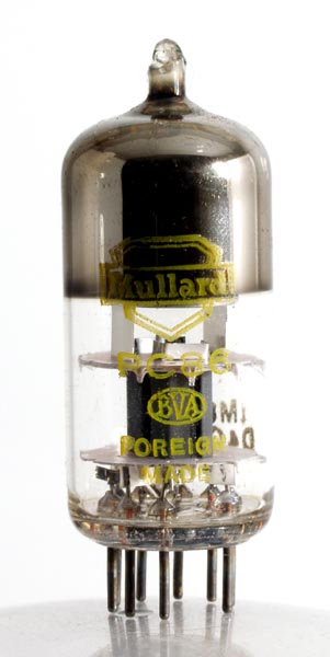
UHF frame grid mixer/oscillator triode, the universal mixer valve in modern UHF tuners.
PC88. (4DL4)
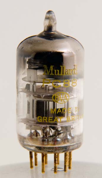
UHF frame grid RF amplifier, companion to the PC86 in UHF tuners. Opinion is divided on the advisability of replacing either of these two types without returning the tuner for realignment. It would appear that in strong signal areas the valves may be replaced in situ.
PC95, PC97
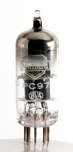
Two frame grid seven-pin RF triodes found in the smaller new VHF tuners. The PC95 is the variable μ valve of the pair but in other respects they will interchange.
PC900
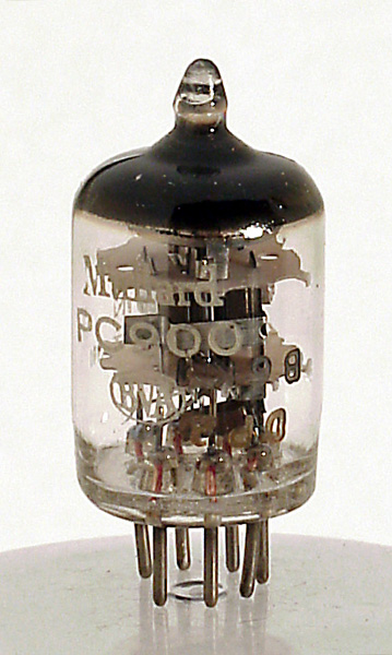
An improvement on the PC97 but with different base connections.
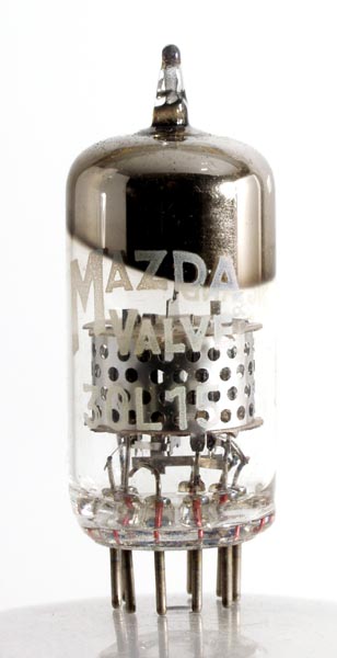
PCC84 (30L1, 7AN7, B319)
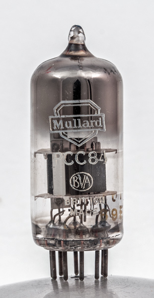 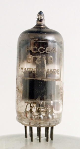 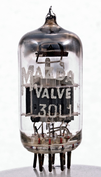 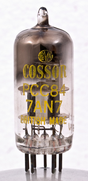
The PCC84 is a double triode cascode RF amplifier with 7.0 V 0.3 A heaters for receivers operating on Bands I and III. Its commonest fault symptoms are low gain and a grainy picture, and in fringe areas have been superseded by the PCC89 and 30L15 valves.
These valves have the same base connections and the same heater current but their mutual conductance is double that of the PCC84, providing a considerable increase in gain, particularly on Band III. Unfortunately it is not possible to use these later types as direct replacements for the PCC84 or its equivalent without alteration to the tuner unit.
The author has found that in many cases a 30L15 will, however, give greatly improved results by merely retuning the small trimmers usually positioned at the top of the tuner or on the individual coil biscuits.
PCC85
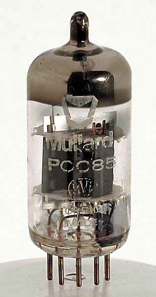
300 mA version of the ECC85 to be found in FM VHF radio tuners in combined receivers.
PCC88. (7DJ8)
The original 'frame grid valve'. Has a wasp waist very reliable. Has the same base as the PCC85 and will interchange.
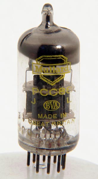
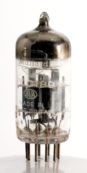
PCC89
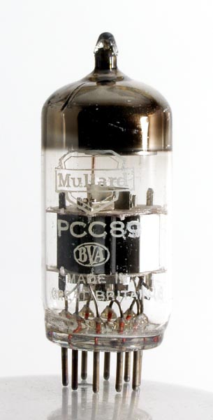
A frame grid double triode cascode RF amplifier with 7.0 V 0.3 A heaters ( See PCC84).
PCC189. (7ES8)
Variable μ version of the PCC88 with the same base and heater details.
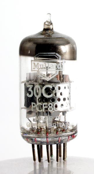
PCF80. (30C1, 8A8)
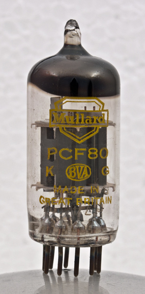
This 9.0 V 0.3 A heater triode pentode was primarily intended as a mixer on Bands I & III tuners but was subsequently used for almost everything else.
A low triode or one, which has been overloaded, may usually be recognised by brown patches on the glass opposite the hole, which is halfway up the triode anode side. Intermittent faults can usually be observed by giving the valve a gentle tap whilst running.
Other fault symptoms are poor signal-to-noise ratio, which indicates a pentode fault, or a weak Band III (or no Band III but Band I satisfactory) indicates a triode fault.
Line multi-vibrator: The line timebase runs fast and will not lock and the line-hold control at the extreme end of its range. The line speed may vary when tapped or during an evening's viewing.
Sync separator-half line oscillator: When used in this circuit pulling on picture (cogging), false line lock and line timebase runs fast may result if the valve is faulty. A negative picture may also occur (if AGC is mean level).
Video amplifier/cathode follower: In this type of circuit a red-hot anode or red-hot G2 electrode may occur. This is not usually due to a faulty valve but to a heater to cathode breakdown on the CRT although the valve's emission will be impaired if the set is run for a while in this condition (See also PCF82).
PCF82. (9EA8, 9U8, 9U8A)
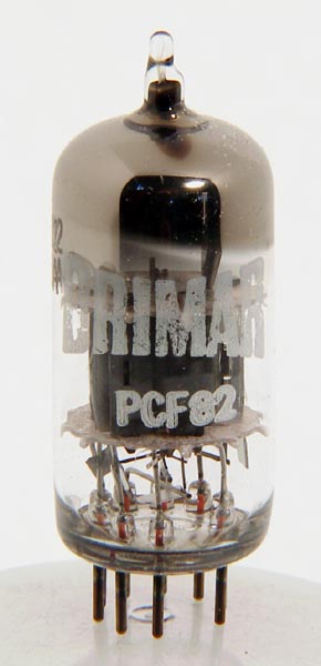
Another mixer with an 300 mA heater, the PCF82 has the same basing as the PCF80 and can be used on higher working voltages than the normal 180 V line. Its characteristics (mainly the triode) are slightly different from the PCF80 but it may be used in its place (sometimes with improvement) in mixer and sync separator stages
PCF86. (8HG8)
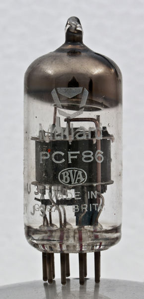
The standard frame grid VHF mixer valve. Has largely replaced the PCF80 in this function but has a different base and will not interchange.
PCF800, PCF801, PCF802, PCF805 & PCF806
 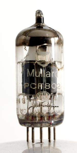 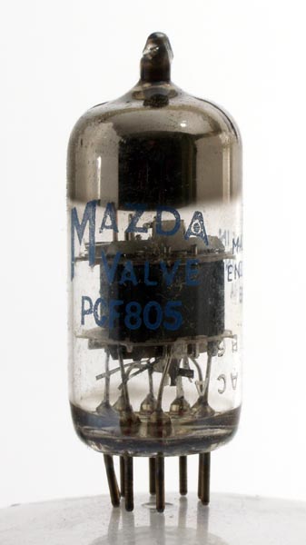 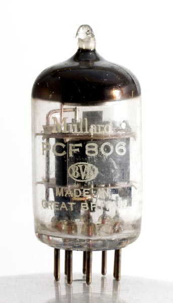
A group of new VHF triode pentodes, all with different base connections and characteristics. The days when tuners were designed around available valves appear to be over.
PCL82
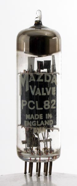
A triode output pentode with 3.5 W output, this valve is used predominantly as a frame oscillator/amplifier.
Its fault symptoms (usually low emission pentode) are cramping at the bottom of the picture, sometimes with fold-over. This condition may correct itself slowly as the valve warms up. For repeated failures of this kind check that the screen grid feed resistor has not changed in value.
Sometimes encountered as a sound output stage, where it gives little trouble. Check feedback capacitors for leakage if distortion is present.
PCL83. (LN309)
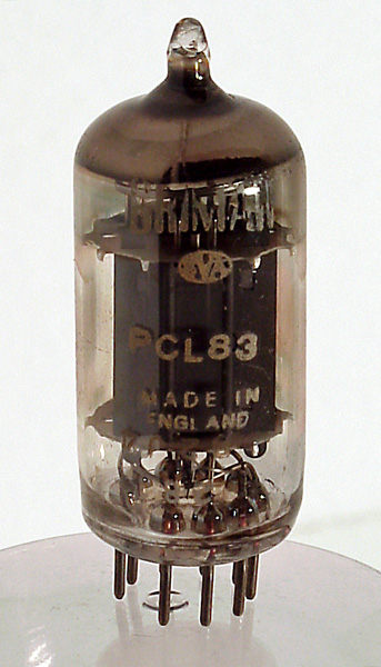
A smaller version of the PCL82 with different basing. Used in a variety of circuits but mainly in the sound output stage or frame timebase. As a sound output valve it commonly becomes microphonic and will probably cut off completely if tapped.
It should also be suspected if hum is present after the interference limiter stage. In an emergency a 30PL1 may be fitted in its place and will give greater output.
PCL84. (15DQ8)
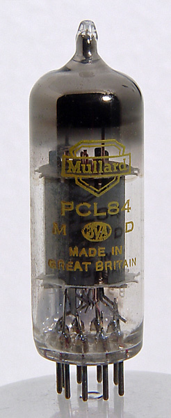
A video output pentode with triode having the same base connections as the PCL82. This valve incorporates a pentode with a higher slope but slightly less power output and a lower impedance triode.
PCL85. (18GV8)
Modern frame output valve with slightly larger triode than the PCL82 and with a different base. Has the same general faults as the PCL82
PCL86. (14GW8)
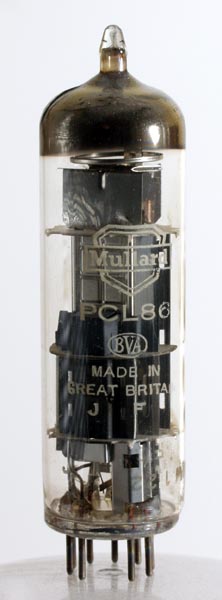
300 mA version of the ECL86 audio valve. It is especially intended to provide good-quality sound output of adequate power in dual-standard sets.
PFL200. (16Y9)
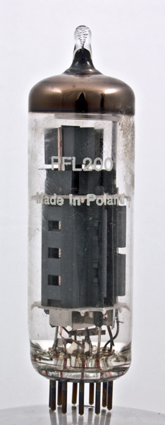
A double pentode. The first issue in the ten pin B10B base to be found in receivers incorporating the new Thorn 900 Cool Chassis. Its output section has the phenomenal mutual conductance of 21 mA/V.
PL36. (25E5, 25F7)
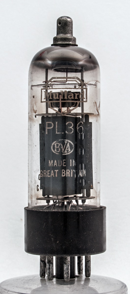
A line output valve on an octal base for 90° cathode-ray tubes. Suitable to replace the PL38 and 30P4 in an emergency.
PL38
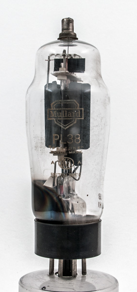
An early octal base line output valve. Fault symptoms are softness, when the valve glows bright purple, not blue, which is apparently normal, and grid sag, which usually burns up the cathode resistor. This latter symptom is more often met when the valve is mounted upside down or horizontally.
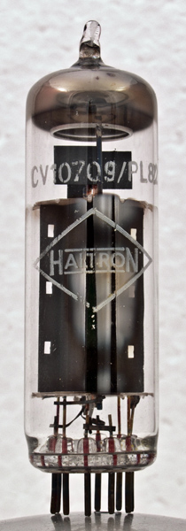
PL81. (21A6, N152, N359)
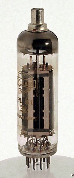
This is a 300 mA heater, B9A based line output valve. The symptoms of low emission are usually a narrow, dim, defocused picture possibly cramped on the right hand side. This does not apply to 110° sets using a desaturated transformer where the valve can age considerably before a deterioration is noticed.
A red-hot grid denotes excessive screen grid current due to a change in value of the screen dropping resistor or insufficient drive.
Heater cathode leakage can produce a 'wasp-wasted' effect and internal shorts are usually marked by bright flashes inside the valve.
An alternative valve is the 21B6 which is slightly fatter and may now be obtained and fitted as a direct replacement for the PL81. It is claimed to be more reliable.
Parasitic oscillation sometimes produces a bright line on the left of the screen on Band III channels and in many cases can be removed by fitting a ferrite bead at the anode or a magnet around the 'waist'.
PL82 (30P16, 16A5, N329)
 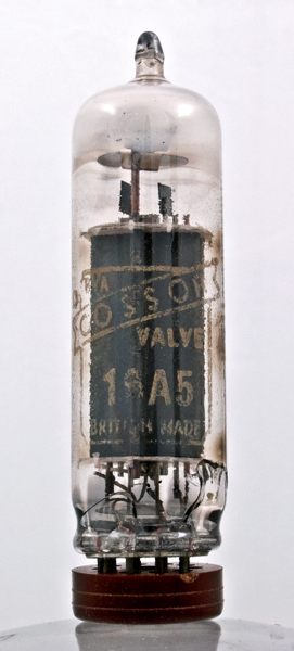 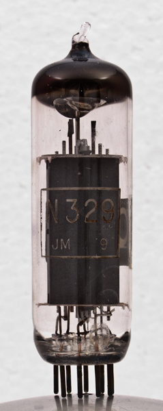
Generally employed as a frame output pentode, the common symptoms of failure are a slow stretching out of the height for a good while after warming up, eventually producing cramping at the bottom of the picture, possibly with fold-over.
This valve may be exchanged with a 30P12 in an emergency, but the difference in bias may prevent correct linearity from being obtained.
PL83. (15A6, N153, N309)
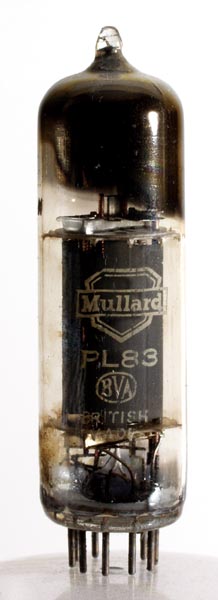
Designed as a video amplifier, in which stage it seldom gives trouble, but often used as a frame amplifier, where it exhibits the same symptoms as the PL82 after a while.
It frequently develops heater cathode leakage , in which case a 'judder' is imparted to the picture, giving the effect of two flickering pictures, one half an inch or so above the other. If these symptoms are combined with fold-over the grid coupling capacitor should be checked for leakage.
PL84. (15CW5 30P18 N379)
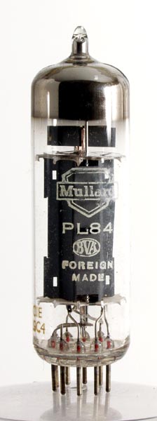
A frame output valve with the same base, connections and heater current as the PL82. Intended for the extra power required by 110° tubes, its chief failing to date has been the production of Barkhausen-Kurz (parasitic) oscillations.
These take the form of a series of bunched scanning lines similar to telegraph wires which move slowly up and down in the middle of the screen (30P18 equivalent).
PL302
See 30P19.
PL820
An improved version of the PL81 for 110° scanning. Has the same base and similar characteristics as the PL81 but handles slightly higher peak voltages. Will substitute for the PL81 but the reverse gives short life.
When Mullard introduced the PL820 in 1954 it was stated that it was designed for projection TV receivers.
PY80. (9X3, U152, U309) & PY82. (19Y3 U192)
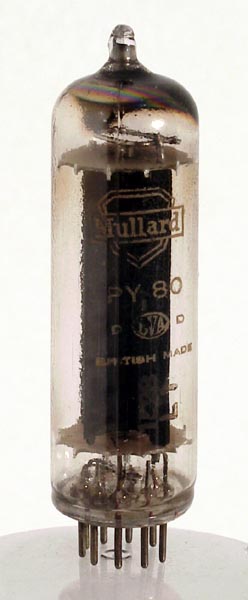 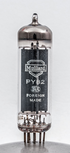
These early 300 mA efficiency diode and HT rectifiers have the same base connections and in an emergency are interchangeable. The PY80 has better heater/cathode insulation but lower HT current rating than the PY82.
PY81. (17Z3, PY800, U153, U329)
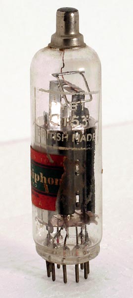
A popular efficiency diode, this valve seldom goes low but may flash over internally due to flaky cathode coating. A red-hot anode can denote an HT short in the line output stage or a heater/cathode short in the valve itself.
Lift the top-cap (cathode) lead from the valve and if the glowing ceases suspect the circuit, but if it persists suspect the valve. (See U251).
PY800
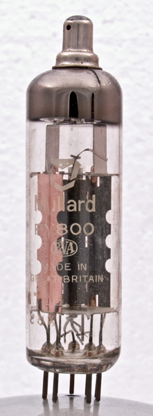
An improved version of the PY81 for 110° scanning. Has the same base and similar characteristics as the PY81 but can cope with higher flyback voltages. Will substitute for the PY81 but the reverse does not always last long.
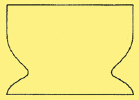
PY32. (PY33, U291)
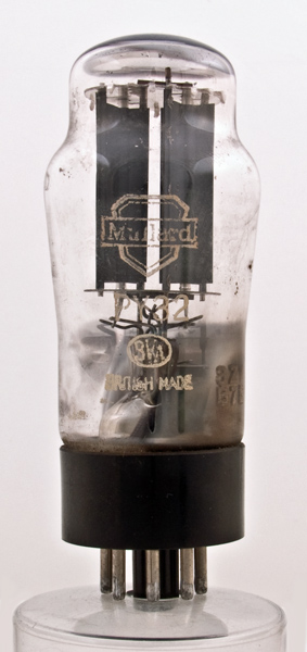
These formed the current HT rectifier for many TV receivers. The early form had a shaped envelope and two separate anodes connected to pins 3 & 5. Later versions have a straight-sided envelope and a single long anode and when this type is used it should be checked that pins 3 & 5 are joined on the valve holder.
Fault symptoms are those of weak HT namely a dim, small, defocused picture and weak sound, all of which take longer to appear than normal. Superseded by PY33.
PY33. (PY32, U291)
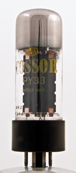
An improved version of the PY32, giving longer life and about 10 V more HT. To be used in place of the PY32, which is being withdrawn.
PZ30. (R14)
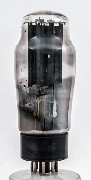
The early HT rectifier, comprising two separate rectifier sections in the same envelope. This led to several manufacturers using one half as an efficiency diode and the other as the HT rectifier, but the trouble that this arrangement caused at first has largely been overcome.
SP41 & SP61
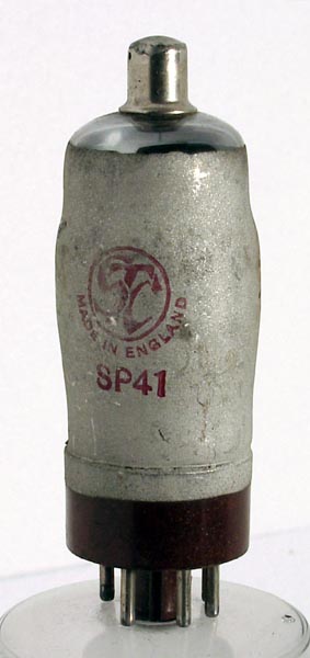 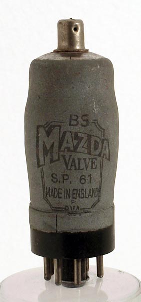
These two are early RF pentodes of similar design but having respectively 4.0 V and 6.3 V heaters. These valves were used widely in early post-war receivers because of their availability from surplus Government stock.
Apart from low emission the major faults are mostly physical, namely intermittent metallising due to the valve becoming loose in its base, a dry joint top cap causing noisy operation and erratic synchronising, weak heater valve holder contacts due to the heavy current drawn.
The offending valve holder pins may usually be taken out and tightened without replacing the entire holder.
T41 & 6K25
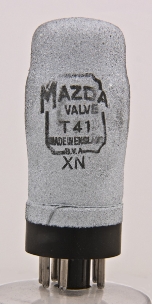 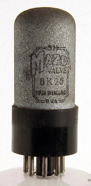
These are Thyratrons. The T41 has 4.0 V heaters and the Mazda octal (MO) base and the 6K25 6.3 V heaters and an International Octal (IO) base. Apart from this they are identical.
Widely used in early post war receivers as line and frame generators but subsequently abandoned due to their non-linearity, comparatively low linear output, and unsuitability for AC/DC techniques.
Commonest symptom is frame judder or dither, usually presenting two complete pictures, one half an inch above the other, both flickering.
U22
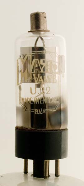
This valve is an EHT rectifier with 2 V 2 A heater and Mazda octal base. It was used exclusively on mains EHT units in vintage receivers. The usual signs of failure are a bright purple glow inside the entire envelope and/or bright white sparks flying from the top and bottom heater. The maximum EHT is 5 kV.
U24
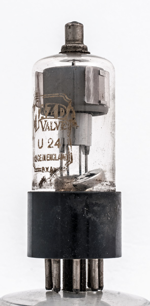
Also an EHT rectifier with 2 V 150 mA heater and international octal base, used in early receivers with flyback EHT. If it is difficult to obtain, change the base and use a U26 or wire in a U25. The maximum EHT is 7 kV.
U25. (2L2, KY50, U47)
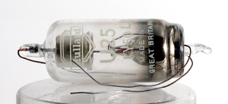
The U25 is a wired-in EHT with 2 V 200 mA heater. Fault symptoms are low emission (a picture that expands rapidly with increased brilliance) and a flaking cathode (ragged edge with width variations and defocusing).
If no gettering can be seen around the top of the bell the valve is becoming 'soft' or if the filaments repeatedly blow, wire a 15 Ω W resistor across the heater pins.
If U25s fail due to internal shorts, check the efficiency diode, which often fails shortly afterwards.
U26. (2J2, KY80, R20, U49)
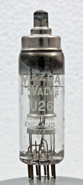
This is the plug-in version of the U25 with a much higher working voltage. Fault symptoms are the same as the U25, for which it may be substituted in an emergency, taking 150 mA greater heater current. This makes it an ideal replacement of the U25 in cases where repeated failures occur in lieu of the 15 Ω shunt mentioned in the U25 section.
U191. (19CS4, PY301, U339,)
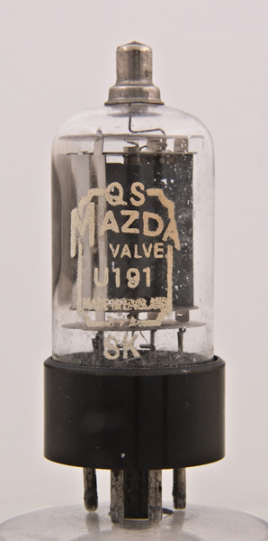
The U191 is a current efficient diode with 19 V 300 mA heater and octal base. Earlier versions marked 'QS' were very susceptible to cathode flaking but the later version marked 'NL' is free of this defect (See U25).
U193. (A61, PY801, U349)
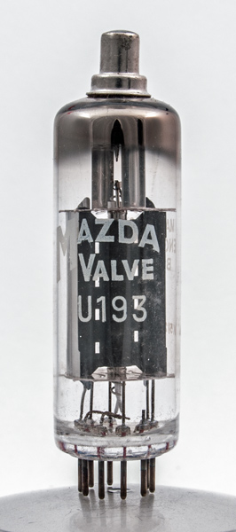
An efficiency diode for use with the 110° tubes. Very similar to the PY800 and the PY81, with which it will interchange. A sign of failure is a gradual increase in width during the warm-up period.
U251
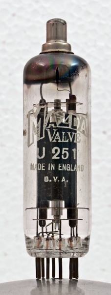
A nine-pin efficiency diode which is equivalent to the U329. It usually fails due to a heater fault. A PY81 may be fitted as an emergency replacement without alteration.
U282
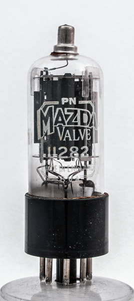
This is an octal-based efficiency diode which is found in receivers in the immediate pre-ITA era. Seldom fails but can be destroyed by insulation breakdown of the heater winding on the mains transformer.
Should this occur the cheapest cure is to earth the heater winding via a 100 Ω resistor and rewire the stage to accept the U301.
U301. (CY30)
An efficiency diode with similar characteristics to the U282 but different basing, the valve is the 200 mA heater equivalent of the U191 and has as its main fault symptoms cathode flaking, causing bright flashes during warming up, and a short-circuited heater (See U25).
U801
An early 200 mA 80 V HT rectifier which has four separate anodes and two separate cathodes. Fault symptoms are purple flashes, open heater and fuse blowing.
Signs of age are loose white powder in bottom of envelope and a metallic patch on the glass above each anode. It is commonly used with 50 Ω or 100 Ω surge limiters in the anode circuits.
These surge limiters should all be checked at the same time as the valve is replaced to ensure that current is taken evenly by all sections. It is now more economic to use two BY100 diodes.
UU8
A 4 V HT rectifier used in early TV receivers. Although spells of trouble with this valve were experienced, many failures were not due to the valve itself.
Condensation between the valve and its holder is a frequent cause of trouble, especially in console models where the power unit is near ground level. 50 Ω surge limiters fitted in each anode leak will often prolong the life of the valve.
6F12
See EF91.
6F19
See EF85.
6F23
A 6 V high-gain pentode which may be used as an emergency replacement for a 30F5 and EF80 in series circuits.
6F24 & 6F25
The modern frame grid IF valves. The 6F24 is the high-gain version of the 'straight' 6F23 and the 6F25 is its variable-mu counterpart.
6F26
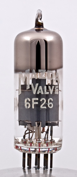
A variable-mu pentode with similar characteristics to the 6F1/EF85, with which it will interchange.
6K25
See T41
6/30L2
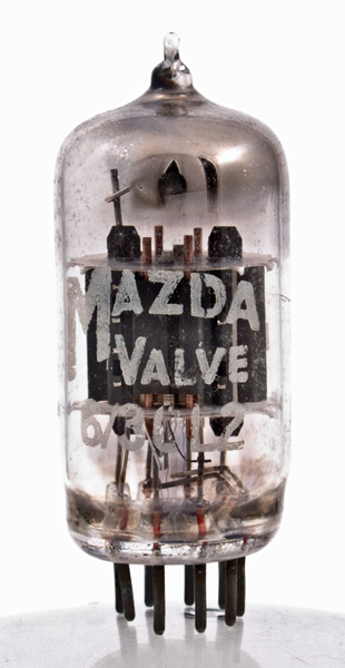
This valve is a general purpose 6.3 V 300 mA double triode. Gives most trouble in timebase circuits where synchronism may take a while if the valve is slow heating.
Faulty valves usually produce a higher timebase speed than normal and also give rise to variable contrast symptoms when faulty in AGC circuits.
For versatility the triodes are equal to each other and also have the same characteristics as the triode section of the 30FL1, 30PL1, 30PL13.
6L18
A 200 mA triode used as a frame amplifier in five-channel sets. Symptoms of low emission in frame timebase are fold-over at the bottom of the screen and a short picture. It may often be exchanged with the less important 'spot wobble' valve where fitted.
6P25
The 6P25 is an early sound and frame output valve. Common faults are open-circuit filament and frame fold-over at the bottom of the screen. Valves suffering from the latter trouble may be change over with the sound output valve if of the same type. Emergency equivalents are 6P1, EL33 or 6V6.
6U4
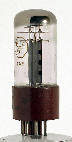
This 6 V efficiency diode frequently develops an open-circuit heater.
10C2
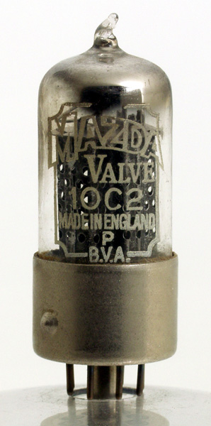
A 28 V 100 mA triode pentode whose commonest fault is that the heater blows soon after switching on. Check the heater voltage of repeatedly troublesome and fit a small resistor across the heaters if necessary to absorb surplus.
10P13. (N118, N145)
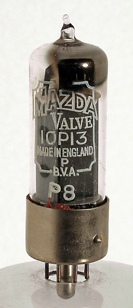
A 40 V 100 mA output tetrode used as a frame and sound amplifier. It has the normal fault symptoms of a frame output stage, i.e. varies when tapped, the bottom of the picture becomes cramped and Barkhausen-Kurz (parasitic) oscillations producing 'telegraph wires' across the centre of the picture.
When withdrawing old 10P13s make sure that the glass envelope does not pull out of the metal base. Should it do so the heater pins are those adjacent to the keyway.
10P14
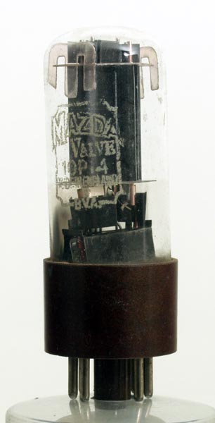
This 40 V 100 mA output pentode is the octal-based version of the 10P13. Used in one receiver as the frame and sound output pentodes in which it is common to find that if one valve fails the other may follow suit.
20D1
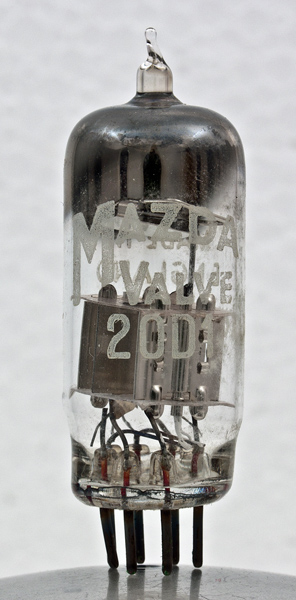
The 20D1 is the 9.5 V 200 mA version of the 6D2 (See EB91 for fault symptoms). A 6D2 may be used as an emergency replacement but it will take longer to heat up.
20F2
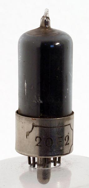
An 11 V 200 mA RF pentode used mainly as a sync separator. It seldom gives trouble except in the frame output stage of one certain receiver. If the valve fails in the sync separator stage a 6F15 may be used as an emergency replacement.
20L1
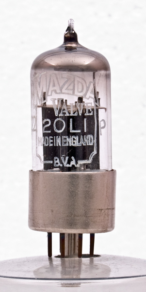
This 12.6 V 200 mA double triode is most troublesome in flywheel sync/line oscillator stages where the symptoms of a low-emission valve is high-line frequency.
Frequently valves of some age are slow heating and involve constant adjustment of the line hold control during the first half-hour. If the verticals are bent suspect heater cathode leakage.
20P1
A 38 V 200 mA line output valve whose low-emission fault symptoms are lack of width with the picture cramped on the right. The emergency replacement is the 20P4, although this may give excessive width and EHT
20P3
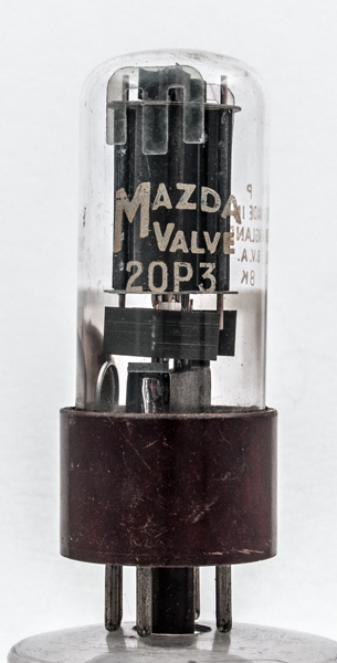
This 20 V 200 mA output tetrode is the 200 mA version of the 10P14. It gives the normal low emission symptoms in he frame timebase, i.e. cramped bottom of the screen (See 10P14).
20P4
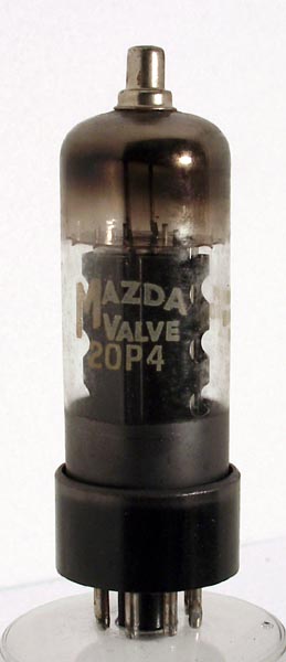
The 20P4 is a 38 V 200 mA line output valve. A smaller and more economic version of the 20P1. In certain receivers with self-oscillating line output stage a specially tested valve coded 'GP' should be used.
20P5
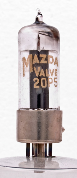
The 20 V 200 mA version of the 10P13 is comparatively trouble free (See 10P13).
30C1. (8A8, 9A8, LZ319, LZ329, PCF80)
See PCF80
30C15. (9EN7, LZ339, PCF800)
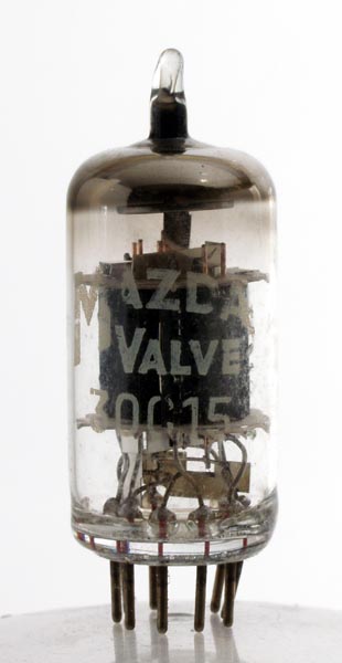
The high-gain version of the 30C1 which cannot be interchanged due to different basing.
30C17. (PCF87)
A variable-mu frame grid VHF mixer similar to the 30C15 and with the same basing. Will interchange in an emergency.
30C18. (7GV7, PCF805)
Another frame grid variable-mu mixer. Characteristics are similar to the 30C17 but the basing is entirely different.
30F5. (7ED7, PF818, Z329)
This is a 7.3 V 300 mA RF pentode. Its high gain occasionally produces an unstable IF stage unless the decoupling if perfect. An EF80 or 6F23 may be used as emergency replacement in series heater circuits.
30FL1. (9GB8, LN339, PCE800)
This 9.4 V 300 mA triode beam tetrode is a general purpose valve with various applications. Works hardest as an AF amplifier/sound output valve judging by the frequent replacements for low gain.
Commonest faults are open-circuited heater and heater/cathode breakdown. The latter may produce perplexing symptoms in VHF TV combined receivers where the offending valve is in the part of the set which is out of circuit on radio. (See also 6/30L2.)
30L1
See PCC84 and 30L15.
30L15
The high-gain version of the 30L1 with almost double the gain on ITV. This valve has the same basing and heater as the 30L1 and has successfully been fitted as its replacement despite the fact that it is not an equivalent.
The present RF trimmers on the turret tuner normally have to be readjusted (usually unscrewed about three turns) but no other alteration appears necessary and the stage does not overheat.
At odd times the substitution of the 30L15 for the 30L1 has produced beat patterns due to self-oscillation on certain channels, but the sensitivity of the receiver in such cases has usually been found sufficient to make the change of types unnecessary. The PCC89 has not been found to interchange well with the 30L15.
30L17
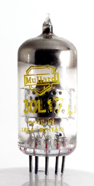
The frame grid version of the 30L15 with the same base as it and the PCC89. Interchangeability depends upon the circuit design but it is worth trying in an emergency.
30P4
This 25 V 300 mA line output valve is the 300 mA version of the 20P4. Like the 20P4 it has a few special batches which have been tested to meet certain requirements. It is interchangeable in an emergency with the PL36.
The 30P4 has the habit of producing spurious oscillations on Band III, especially in the timebases designed for wide-angle scanning. These take the form of ragged vertical lines on the left of the picture and may be cured by substitution or by fitting ferrite beads in the anode lead. (See also 30P19.)
30P12
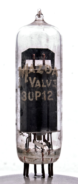
This 12.6 V 300 mA tetrode is a 300 mA equivalent of the 20P5. It suffers the usual troubles of a frame output valve, namely microphony and cramped picture at the top and bottom.
Sometimes it exhibits bright flashes when tapped. It is interchangeable in an emergency with a 10P16 (PL82), preferably with adjustment of bias.
30P16
See PL82.
30P18
See PL84.
30P19
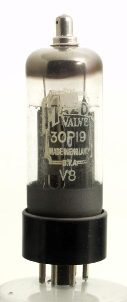
The 110° version of the 30P4, which it supersedes in every case except the single valve Murphy V310 series, where a 30P4 MR must be used.
30PL1. (13GC8, LN319, PCL801)
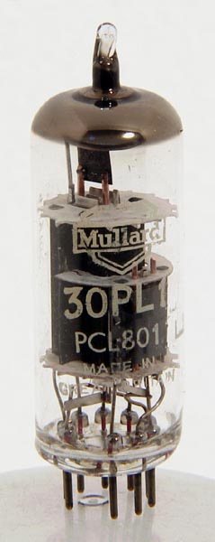
This 13 V 300 mA triode beam tetrode is a useful sound amplifier/output valve with 5 W output and widely used in frame timebases up to 90° scanning angle.
The triode section seldom gives trouble but the tetrode suffers the normal symptoms in frame timebases, i.e. the picture take a long time to reach full height, is cramped at the top and bottom, and the picture jumps when the valve is tapped.
It will replace the PCL83 in an emergency but the reverse does not always apply.
30PL13. (16GK8, PCL800)
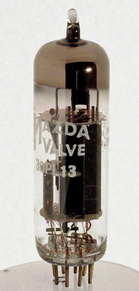
A 16 V 300 mA triode beam tetrode which is the 110° scanning angle version of the 30PL1. It exhibits the same fault symptoms, plus the vertical 'judder', which may not occur until an hour or so from switch-on and is preceded by lack of interlace.
RF pentode substitution notes
Readers ask 'What will happen if I substitute a variable-mu pentode for a straight pentode or a frame grid valve for an ordinary one?' As most RF pentodes have the same base and heater consumption there is no objection to trying and little harm can be done.
Generally speaking the stages have been designed to squeeze the last ounce out of the valve selected and the substitution of a wrong type can give less rather than more.
Fitting a straight pentode in a variable-mu stage usually gives an abrupt action to the contrast control, whilst a variable-mu valve in a straight stage should lower the gain.
By replacing a valve with its frame grid equivalent an improvement in gain can usually be obtained. A little realignment and bias adjustment is often necessary. Sometimes the different characteristics outweigh the extra gain and no improvement results. Sometimes the gain is so greatly improved that the stage becomes unstable and oscillates.
The concluding part appeared in the September 1965 edition of Practical Television and many thanks Roger Lawson to for sending scans of the pages.
|