|
PL82Sensibly equivalent¶ to:See also:
|
|
|
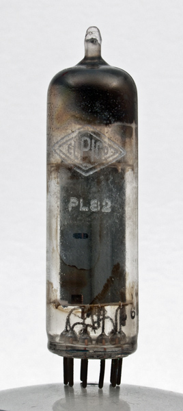
This exhibit is a PL82 that clearly demonstrates what happens to a valve in a domestic television receiver. It has been partly cleaned but still some of the grime remains. The large amount of heat generated caused a considerable convection current through the set and the high EHT voltage encouraged dirt and grease to settle. It was much worse in a house where tobacco smoke or open fires were common.Although the PL82 would normally be found in frame output stage of a television receiver, a pair used as an audio amplifier in push pull class AB1 would deliver 9 Watts at 4 % distortion.The peak to peak grid signal voltage would be 26 Volts and the shared anode load would be 4,000 Ohms.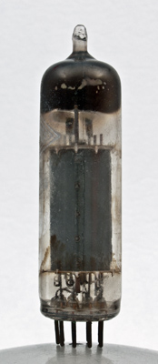
The closed anode and grid cooling fins above the top mica.The thin glass tube envelope is 20 mm in diameter and, excluding the B9A base pins, is 71 mm tall.References: Data-sheet & 1040. Type PL82 was first introduced in 1951. See also 1951 adverts. |
Pin Connections
| 1 | 2 | 3 | 4 | 5 | 6 | 7 | 8 | 9 |  nc | g1 | k,g3 | h | h | ic | a | ic | g2 |
|
|
Absolute Maximum Operating Conditions
| Vh | Ah | Va | Vs | Vg | mAa | mAs | ra | gm | Pout | D | 
| 16.5 | 0.3 | 170 | 170 | -10.4 | 53 | 10 | 20,000 | 9.0 | 4W | 10% |
|
Updated January 03, 2022.
|
|