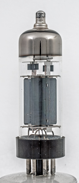
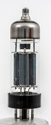
The PL36 was designed for service as a line timebase output valve in television receivers and is designed for series heater chain use. It has a 6.3 Volt parallel heater version the EL36.
The maximum positive peak voltage on the anode is 7 kV and the screen dissipation is up to 5 W.
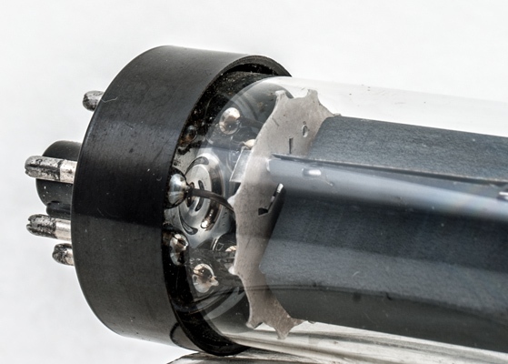
The end wall of the anode looking along the grid axis. The side flanges are placed at the point of maximum heat generation.
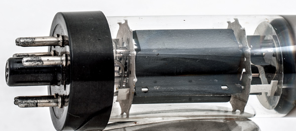
The glass foot base. In the later PL500 the B9D base completes the transition to the all glass type with pins replacing the wires used in the glass foot construction that later had to be soldered into the IO base cap.
The beam plate visible inside the anode. The control grid has heat sinking fins at the top.
The wide glass tube envelope is 29 mm in diameter and, excluding the IO base pins, is 93 mm tall.
References: Data-sheet, 3002, 1040 & 1043. Type PL36 was first introduced in 1955. See also1955 adverts.