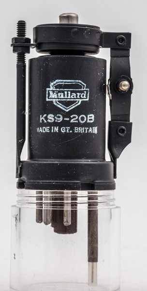
The KS9-20B Klystron was designed for microwave RF generation of about 20 mW at 9-10 GHz. The exact frequency range is given by the suffix letter but we have not found the range indicated by the suffix letter B.
This reflex klystron produces a continuous output and can be modulated for communications use but is mostly used as the local oscillator in a radar receiver.
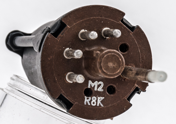
The output power is taken from the probe by passing the tip into waveguide. The base for this valve is special but an International Octal holder with pin four drilled out is equivalent.
The electrons pass from the cathode through the resonator and some pass on to the negatively charged reflector. The reflector voltage is arranged so that the velocities of the electrons reflected back into the resonator will set up oscillations. The resonator cavity is mechanically tuned and at the correct voltages RF is produced at the probe. The voltages are adjusted for maximum output. Klystron frequency will change rapidly for small changes of voltage or temperature. Thus these devices are required to operate from stabilised supplies and be isolated from temperature fluctuations.
To obtain frequency modulation is simple, a small modulating voltage is superimposed on the DC of the reflector. Early amateur radio on the 3cm Band used this type of klystron with modifications to raise the operating frequency to 10GHZ or above.
Typical operating voltages are: cathode grounded, resonator at +300 V at 25 mA, and reflector at -100 to -200 V at 5 uA. The klystron produces RF with the mechanical tuning and reflector voltage at quite critical points. Several RF producing conditions existing for a particular valve. The strongest being the one chosen.
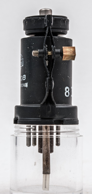
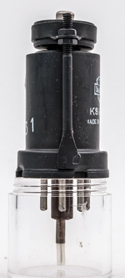
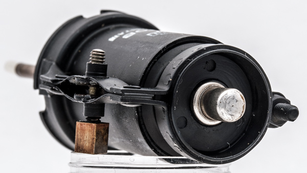
The mechanical adjustment acts on a pair of steel strips that are moved apart by the screw action. This movement is passed to the top of the valve where corrugations in the envelope allow a small change in the internal cavity size. See also723A/B that shows a similar klystron cut in half.
The bellows frequency adjustment mechanism. The square end fits into a socket that couples to the front panel via an insulated rod or flexible mechanism.
The Pulling the oscillator outside the maker's range involves moving the right hand arm of the reflector.
The fixed arm of the reflector or repeller.
The top of the envelope with reflector connection. The adjuster mechanism uses clockwise and anticlockwise threads to make the strips move out or in.
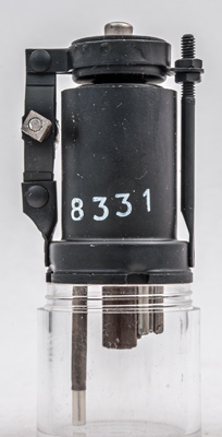
The base. The socket would be mounted on waveguide 16 so the the probe can couple energy into the guide.
The thin metal tube envelope is 26 mm in diameter, and excluding the IO base pins is 57 mm tall.