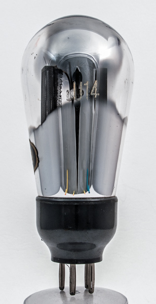
Initially the U14 and the U12 were the same valve intended to meet all HT requirements up to a maximum of 120 mA at 500V, using a capacitor-input filter. However, some valves performed better than others on final factory test so the best ones were graded and marked U14 whilst the also-rans were marked U12.The U14 was designed to work with a maximum reservoir capacitor of 32 µF and to have an effective series resistance of 100 Ohms.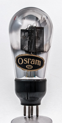
The Osram paper label and the pair of mesh anodes with glass rod support between.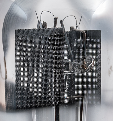
The ribbon filaments are tensioned with single wire springs that are fixed to stout supports that are in turn embedded within the central glass rod. The horizontal glass rod is supported back to the pinch by a central rod that also carries the anode fixings.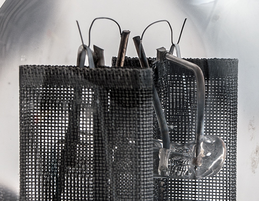
A closer look at the woven anodes.The balloon envelope is 56 mm in diameter and, excluding the B4 base pins, is 120 mm tall.References: Data-sheet & private communication. Type U14 was first introduced in 1931. See also 1931 adverts. |