|
PL82Sensibly equivalent¶ to:See also:
|
|
|
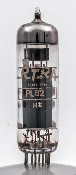
The PL82 would normally be found in frame output stage of a television receiver but a pair used as an audio amplifier in push pull class AB1 would deliver 9 Watts at 4 % distortion.The peak to peak grid signal voltage would be 26 Volts and the shared anode load would be 4,000 Ohms.RTRA stands for the Radio Trades Retailers' Association which was formed in 1942.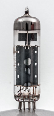
The control grid heat sink is quite large. Through the holes in the anode it can be seen that there are three wire grids inside. Whilst it is difficult to see the control grid shape, the screen grid passes flat across the cathode.The thin glass tube envelope is 21 mm in diameter and, excluding the B9A base pins, is 70 mm tall.References: Data-sheet & 1040. Type PL82 was first introduced in 1951. See also 1951 adverts. |
Pin Connections
| 1 | 2 | 3 | 4 | 5 | 6 | 7 | 8 | 9 |  nc | g1 | k,g3 | h | h | ic | a | ic | g2 |
|
|
Absolute Maximum Operating Conditions
| Vh | Ah | Va | Vs | Vg | mAa | mAs | ra | gm | Pout | D | 
| 16.5 | 0.3 | 170 | 170 | -10.4 | 53 | 10 | 20,000 | 9.0 | 4W | 10% |
|
Updated January 03, 2022.
|
|