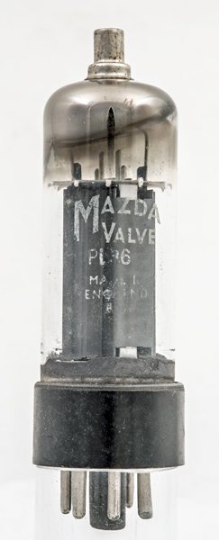
The PL36 was designed as a line timebase output valve for television receivers. The valve was a popular design and made by several companies. We also have a Mullard exhibit of the PL36 as well as a NOS Mazda PL36.
The design dates to the 1950s, when sets were black and white and screen sizes of 14 - 17 inches diagonal was common.
The maximum positive peak voltage on the anode is 7 kV with a 10 W dissipation. The screen dissipation is up to 5 W and the grid is designed to withstand negative peaks of 1,000 Volts.
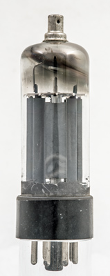
The anode is a closed box in this Mazda example rather than made with more open sides. The beam plates can be seen in this view along the grid axis.
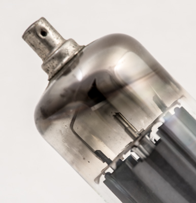
The single mica disc at the top with the anode connected to the top cap.
The wide glass tube envelope is 29 mm in diameter and, excluding the IO base pins, is 92 mm tall.
References: Data-sheet, 3002 & 1040. Type PL36 was first introduced in 1955. See also1955 adverts.