The CV1479 is an S Band cavity magnetron. There are four fixed frequency versions in the series CV1479 - CV1482 and all are based on the M501. The CV1479 is nominally on 3.045 GHz.
There is no maker's name on the valve but the box was sealed with GEC M-OV paper tape.
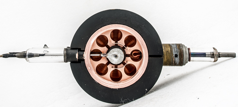
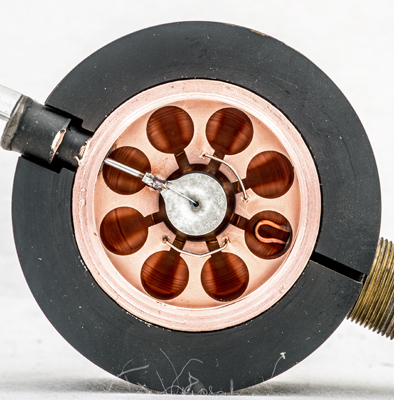
The central anode has been machined from a copper block and the end plates are also copper as can be seen from the back plate that is still present. This cavity magnetron has been opened to reveal the inner structure. The eight cavities surround a cylindrical cathode with central heater. The output is taken from one cavity to the probe on the right. The probe would be located within waveguide and maintained at earth potential. The heater and cathode would be at -27 kV during the pulse. To reduce arcing like poles are strapped together.
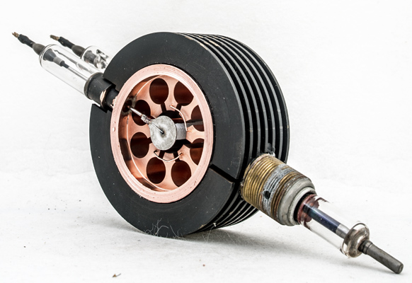
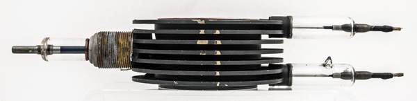
The typical shape of these early cavity magnetrons. The fins for cooling are 75 mm in diameter and 30 mm front to back. The glass tubes are 11 mm in diameter and the overall length is 194 mm. The oxide coated cathode can be seen under the end plates. The heating power is similar to an HT rectifier but the cathode is much larger as the peak current is very high.
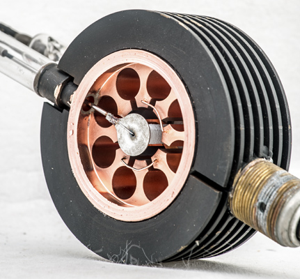
A closer view of the central cavities.
The back plate has been turned. The output loop can be seen to have been soldered at one end to the main copper body. The straps are fixed into square holes and are raised from the main copper block.
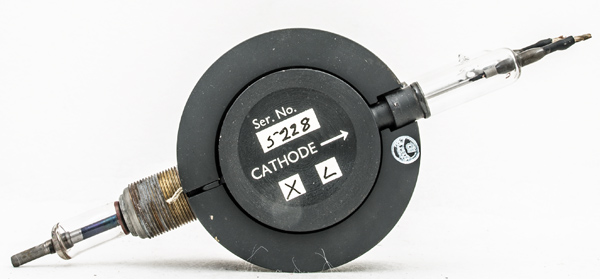
The other side has the closing plate in place. The cathode connection is indicated and the serial number is 5228. The powerful magnet poles are placed either side of the central cylinder.
Side view of the radiator fins and the evacuation pip is on the right. Note that these magnetrons were pumped to a high vacuum without the use of gettering. This was typical of valves for use at very high voltages to avoid insulation breakdown.
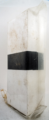
We have two of these magnetrons. This one is still sealed within the original polythene bag. The outer container is thick cardboard.
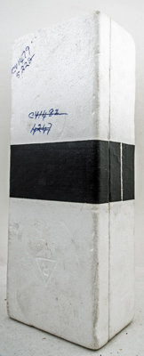
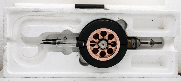
Our other example inside the shaped expanded polystyrene protection. The two parts being held together with adhesive tape.
For this display version the external braided leads have been removed but the space for them is visible in the packing. The two finger holes enable the valve to be removed from the polystyrene into which it is a push fit.
The wide metal tube envelope is 51 mm in diameter and, excluding the base pins, is 33 mm front to back.