|
This amplifier advertised on ebay claims a better performance than the mini 6P3P amplifier. This has a conventional power supply whereas the mini has a switched mode power supply - it also performs really well.
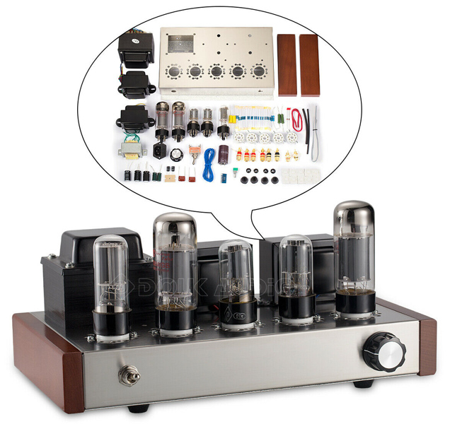
The amplifier as advertised on ebay.
The amplifier cost £210.00 in December 2019. The design is single ended and the claimed output is seven watts per channel at 1% distortion. The frequency range at the three dB points is given as 10 Hz - 70 kHz. The signal to noise ratio is given as 95 dB.
The amplifier arrived well packed and protected in a tri-wall cardboard box. The valves were individually wrapped and the five valves were further protected within the box by being held in a cardboard tube. This tube was hard cardboard and 6 mm thick. The ends were covered in adhesive film. The 6P3P valves were in the shouldered envelope rather than the advertised tubular one. The transformers were wrapped in soft plastic foam film. All the small components and nuts and bolts came in a resealable plastic bag.
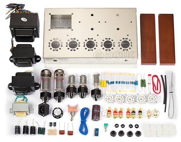
The full kit as advertised.
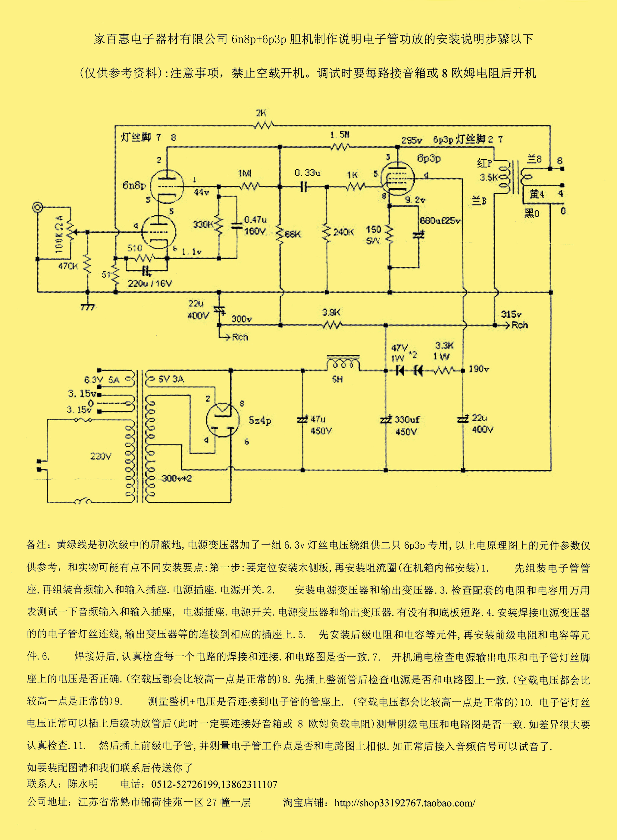
The circuit has a cascode double triode voltage amplifier (6N8P) driving the 6P3P output valve. The gain with the double triode is sufficient to allow for the application of negative feedback to improve the overall performance. The S/N ratio is given as 95 dB, the distortion is claimed to be less than 1% at full power and frequency response, at the -3 dB points, is stated as 10 Hz to 70 kHz. Each channel is quoted as having a full power output of 7 Watts. The power supply uses a 5Z4P full wave rectifier.
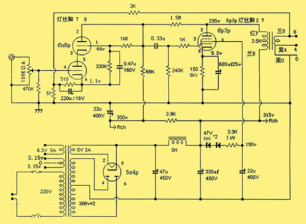
The full circuit diagram.
The feedback loop does not contain a capacitor shunting the feedback resistor and this would account for the extended HF response. The voltage amplifier valves are heated by a 3.15 - 0 - 3.15 Volt winding and the output valves have a separate screen grid supply at 190 Volts.
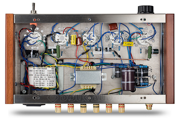
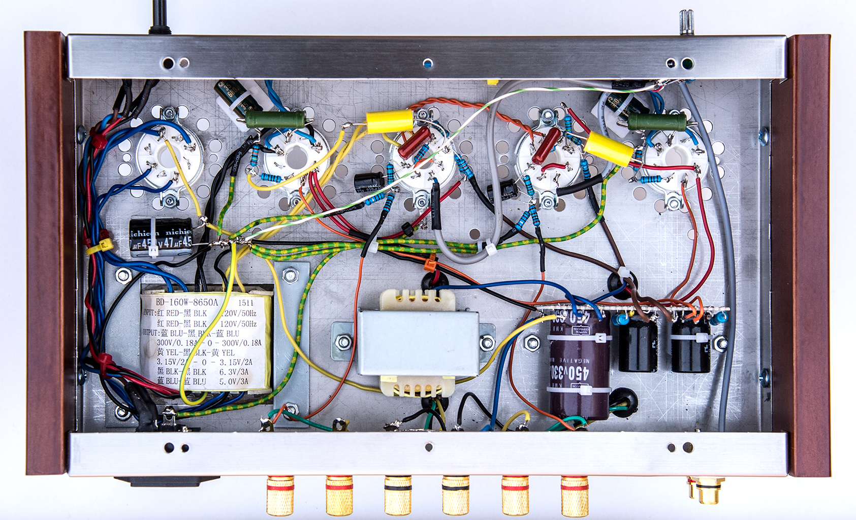
This under chassis photograph and the circuit diagram are the only documentation.
Construction
The first task is to fit the wooden end plates, these fit flush at the top. The boards came with a lacquer finish but no pilot holes. A band clamp was used to hold the wood in the correct place relative to the metal chassis. The holes were traced with a marker and the clamp removed. Pilot holes were drilled the clamp re-fitted and the screws fixed. The stainless steel chassis is made from 0.8 mm sheet and so the edges are sharp and care is required when tightening the wood screws to avoid cuts. Have the chassis on a soft cloth or similar as it will scratch very easily.
Fitting the input sockets revealed a small problem - the raised part of the nylon insulator was thicker than the chassis. The result was that the socket could not be tightly secured. Using a needle file and gentle pressure reduced the thickness to the correct size. The socket(s) could then be securely fixed with a pair of 12 mm spanners.
The speaker sockets fit without having to thin the insulating grommet. Placing a small screwdriver through the cable hole holds the socket whilst the nuts are tightened by a 7 mm ring spanner.
The mains input socket has the letters L, N and E clearly marked. Fit this next.
The valve-holders attach by a ring and two nuts and bolts. The first nut and bolt can be started without the holder in place. Slip the holder in place and gently tighten. Holding the nut in small pointed pliers is useful. With a screwdriver on the topside tighten some more. The ring is now held proud of the chassis and this makes it easier to hold the second nut in place. The bolt can be started in the nut by hand. Finish the tightening so as to equalise the force on both sides of the ring. After five holders this becomes much easier.
The transformers are fitted next. The mains transformer is clearly labelled when mounted. One bracket of the choke shares the hole for the output transformer. The other side has a separate hole. Both output transformers share the central hole. Four grommets are provided to protect the output transformer wires as they pass through the chassis. The output transformers have the wire colours printed on the transformer base. The blue wire goes to the HT line and the red wire to the valve anode. On the secondary: black lead is return, Yellow is 4 Ω and the green wire is the 8 Ω connection.
Initial wiring-up involves the AC connections from the mains transformer and the output transformer leads to the back panel connectors. The supplied mains switch is a SPST type. A double pole single throw rotary mains switch enhanced the visual appearance of the amplifier. An ebay supplier was found with knobs that matched the original. The 50 Hz AC leads are twisted to cancel the external magnetic field as far as possible.
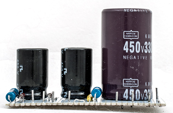
The smoothing circuit board.
The reservoir capacitor is mounted between the rectifier valve base and the mains transformer and secures to the chassis with a sticky fixer and cable tie. The HT centre tap is connected to the negative plate as are the centre tap of the double triodes heater circuit and the mains transformer electrostatic screen. This keeps the main HT ripple current around the rectifier. The smoothing choke connects to the positive plate.
The smoothing and screen grid supply components were mounted on a small piece of strip board. The 330μF capacitor has PC mountings rather than leads or traditional eye tags and the strip board eases the physical assembly. The sticky fixers and nylon ties hold the board to the chassis.
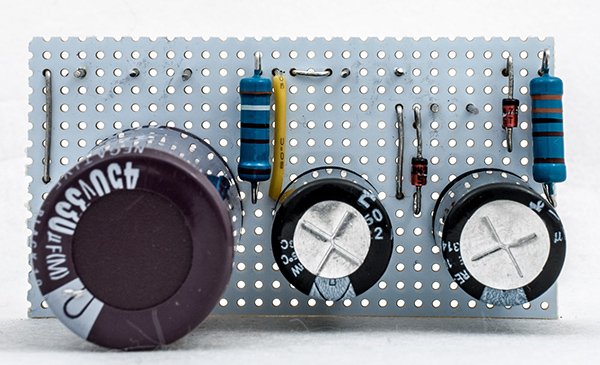
The smoothing circuit board.
The output valves are wired-up next. The cathode bypass capacitor is secured to the chassis with a sticky fixer and cable tie. The cathode resistor sits above the valve holder away from other components. VHF technique is employed, that is all the ground points of the section are brought to a single point and then that point connected to the negative return line. The grid stopper resistor is mounted as close to the valve holder pin as possible.
The voltage amplifier stages are wired next. The components are light enough to be self supporting on the valve holder tags.
The volume control is a miniature type and a small PCB is provided that gives adequately spaced connection points. It was decided to wire up the potentiometer board out of the chassis for better access. The input stage grid resistors were mounted on the PCB. Screened cable was included in the kit and this was sufficient to reach from the input sockets to the potentiometer board. Screened cable was used from the potentiometer board to pin four on the valve holders. This screened cable was connected to ground at the PCB only.
The final stage of construction is the ground wiring to a common point, the feedback wires to the valve holders and a few more cable ties.

This under chassis photograph of the complete amplifier.
Testing
Is the amplifier complete? This question leads to a full check of the physical circuit against the schematic or circuit diagram. Especially all the ground connections.
As this is mains powered there are places under the chassis that are lethal. The age old safe method of testing applies - keep one hand in your pocket or behind your back. Do not risk a circuit across your chest that could stop your heart. The ground connection to the voltmeter is clamped in place and the probe applied with the free hand.
Without valves inserted the power was applied and the AC voltages checked. This ensured that the heater secondaries were wired correctly and that the HT leads connect to the right pins on the rectifier valve holder.
Power down and insert the rectifier. Power up and watch the DC voltage across the main smoothing capacitor. Off load this will be higher than expected and at 415 Volts (and rising) the power was disconnected.
Connect speakers and an input source. The supplied output connectors accept wire or banana plugs. Standard 4 mm plugs are too large. Insert the rest of the valves and power up. There should be no obvious hum. With an audio tone applied to one channel listen for a pure sound. Repeat with the other channel. Power down, discharge the capacitors through a resistor and check for any overheating.
On the amplifier built for this article mains hum was only audible with an ear pressed to the loudspeaker. Impressive.
One note of caution. It is too easy to wire the potentiometer the wrong way round. The double sided PCB has lettering on both sides.
When powered up the main HT voltages were measured. 338 (315) Volts on the smoothing capacitor, 321 (300) volts to the input stage and 216 (190) volts on the output valves screen grid supply. The figures in parentheses are the values given on the circuit diagram.
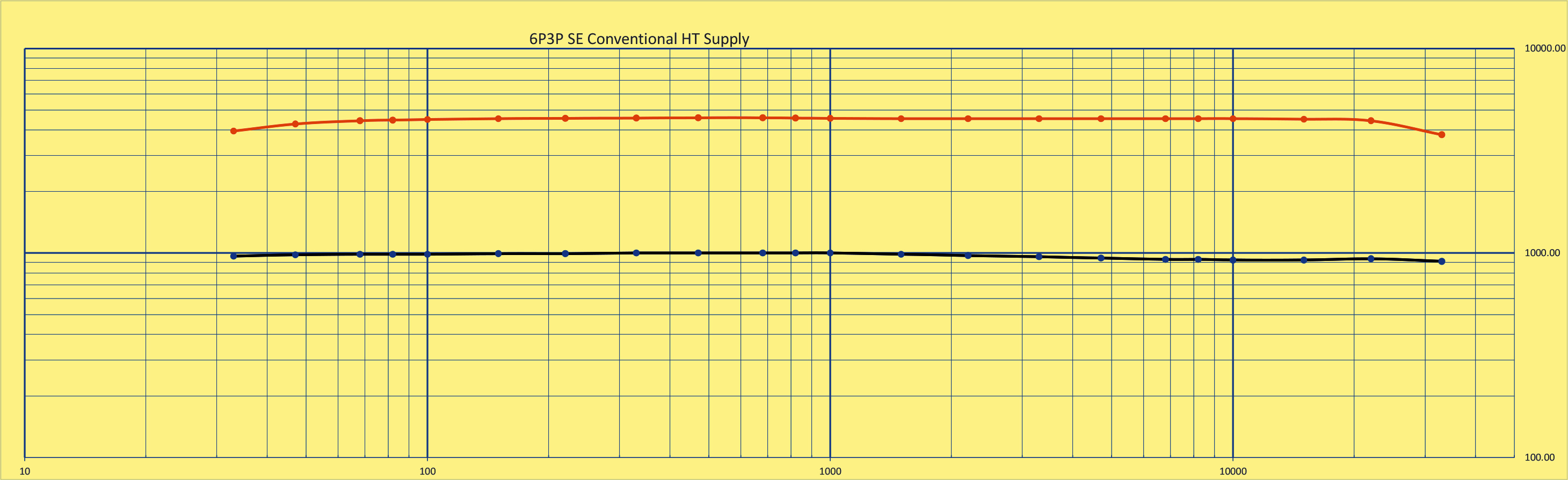
With an eight Ohm load on one channel and the Mission speaker on the other, output testing commenced. The function generator was connected to the channel with the dummy load and the input to the other channel was shorted. The measurements were taken on an IDM203 true RMS meter and viewed on the Tektronix TDS 2012 oscilloscope. The output was set to 1 Watt at 1 kHz sine wave and then stepped through the frequency range.
Next the amplitude of the input signal at 1 kHz was increased until the oscilloscope trace just showed some flattening of the trace. This was 6.04 Volts RMS. This corresponds to 4.5 Watts into 8 Ω. As sine wave testing on a cathode biased amplifier gives a slightly low reading, the actual undistorted output was 5 Watts. In use at high volumes some distortion would not be noticeable and so peak output will be above 5 Watts.
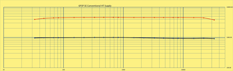
The response of the amplifier. Black = at 1 Watt RMS, Orange = 5 Watt.
Conclusion
The audio output, to my ears, sounds excellent with the Mission bookshelf speakers. Subjectively, the sound seems more open and deep compared to the 6P3P mini amplifier.
In use the amplifier is silent with no input signal.
For an in-depth subjective testing the amplifier replaced the 6P3P mini amplifier on the writer's desk. The source being the audio output from the HP Elitedesk computer and the speakers being the Wharfedale Diamond 9.1 pair.
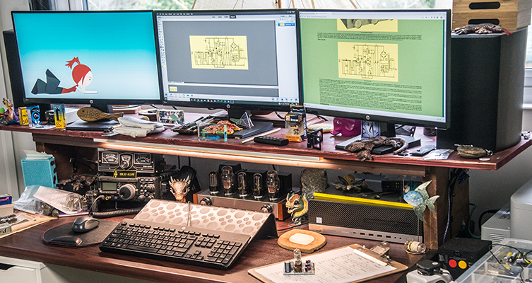
The amplifier in place on the writer's cluttered desk.
The amplifier works well with the speakers and the sound is excellent. There is a depth to the sound that the other amplifiers that have sat on the desk have lacked. As the background is silent, the dynamic range can be fully experienced. Quite simply a magnificent amplifier that has exceeded expectations.
|