|
4215ASensibly equivalent¶ to:See also:
|
|
|

|
The Western Electric 'Weco' valve came in three sub-types, green spot, orange spot and the red spot version that we have.In the UK Western Electric valves were made by STC and given the initial digit 4.The filament is given as 0.8 to 1.1 Volts at 0.25 Amps. The anode voltage was quoted as 15 to 30 Volts for the orange spot, and 30 to 60 Volts for the other two types. The red spot was designed to operate with a grid bias of -3 to -5 volts and used as an RF amplifier. The green spot was designed as a detector with the grid at -7 to -10 volts. Finally the orange spot type was specified as an audio amplifier and to be biased to -3 to -5 volts. All three types were introduced in 1925, had an ra of 25K Ohms, a mutual conductance of 0.22 mA/V and an amplification factor (μ) of 5.5.A visual inspection reveals a glass top support for the fixing rods. The filament is a single vertical wire down the centre of the tubular anode cavity. The grid is wound as a helix in a wire much thicker than the filament.The side markings show patents in 1915 and 1921.We have also been told that these valves were used in early Western Electric microphones.
The base showing the four small pip contacts and the locating pin can be seen on the left.
The grid is in close proximity to the anode with a single thread filament running down the centre of the wire helix.
The side view of the small tube envelope showing the red type indicating spot.
The gettering silvering on one side obscures the electrodes but seen from the other side the anode can be seen.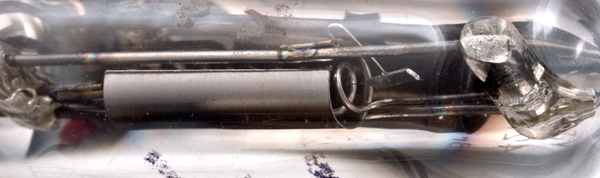
The top of the anode showing the grid and central filament. The filament is attached to a spring, to add tension, and then to the main support strut. The latter also fixes to the glass bead that secures the top of the grid and maintains its position within the anode.The thin glass tube envelope is 15 mm in diameter and, excluding the base pins, is 63 mm tall.References: 1003 & data-sheet Type 4215A was first introduced in 1923. See also 1923 adverts. |
Pin Connections
| 1 | 2 | 3 | 4 |  g1 | f | f | a |
|
|
Absolute Maximum Operating Conditions
| Vh | Ah | Va | Vg | mAa | ra | μ | 
| 1.0 | 0.25 | 60 | -3 | 1.0 | 25,000 | 6 |
|
Updated September 28, 2017.
|
|