|
5Z4GSensibly equivalent¶ to:
|
|
|
|
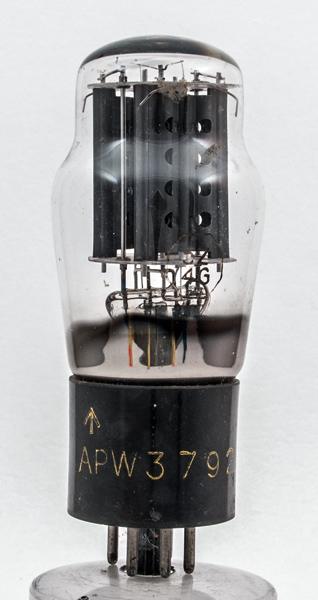
The 5Z4G is a full wave rectifier. Professional equipment, including radar, etc., sometimes required circuits in which valve cathodes carried large signals and had to 'float' at voltages well below that of the chassis. Glass-envelope '-G' versions of common types were therefore required. The metal envelope valves had to have the outer envelope at below cathode potential to prevent them acting as an anode so were at a disadvantage.Initially, these '-G' versions were larger than their metal counterparts but with the introduction of 'pinchless', slimline '-GT' types 5Z4GT the advantage of the compact metal types was reduced to the point where RCA decided to phase out production in favour of (slightly cheaper) all-glass types.Type U52 is given as an 'equivalent'. This is not strictly true although both types have comparable ratings and compatible pin connections. Type U52 is directly heated and will therefore provide its full output within a second or so from switch-on from cold, ie. before other (indirectly heated) valves in the set are ready to conduct.The likely result is a damaging HT surge for at least several seconds each time the set is switched on. Type 5Z4 is indirectly heated and although heater and cathode are internally connected, the heater-cathode insulation is deliberately thickened so that the rectifier's cathode heats slightly more slowly than the other valves, thus eliminating HT voltage surges.Designed to supply equipment of up to 40 Watts total power, this rectifier was made by several manufacturers. This suggests a very popular type, and one that found use in military equipment during WWII.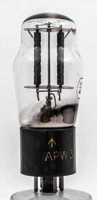
The insulated single stand heaters are run in parallel with the top ends connected to the central rod.
One anode full face.The classic envelope is 44 mm in diameter and, excluding the IO base pins, is 100 mm tall.References: Data-sheet & 1040. Type 5Z4G was first introduced in 1940. See also 1940 adverts. |
Pin Connections
| 1 | 2 | 3 | 4 | 5 | 6 | 7 | 8 |  m | h | nc | a(2) | nc | a(1) | nc | h,k |
|
|
Absolute Maximum Operating Conditions
| Vh | Ah | Va | mAa | 
| 5.0 | 2.0 | 350 | 125 |
|
Updated January 12, 2016.
|
|