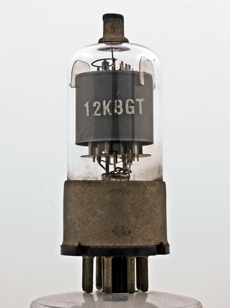
The 12K8GT was purpose designed as a frequency changer valve for use in the broadcast bands. It has a common cathode and is unusual within our collection in that the triode and hexode control grids are internally connected.
The local oscillator would produce 7.5 Volts peak to peak signal from the triode section.
The input signal would be coupled to the frequency changer via the top cap connection to grid 3 thus maximising oscillator and signal circuits. The micas are shaped to fit the envelope and hold the electrodes firmly. The notched grid supports can be seen.
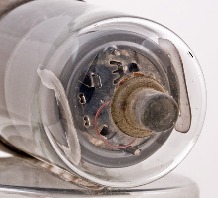
Seen from the top of the base skirt the image reveals the pinch and connections to the main assembly. The heater wire is welded to the supports and as it rises to the cathode the insulating coating is visible as a thickening of the wire.