|
VT105Sensibly equivalent¶ to:CV1105 ML6See also:
|
|
|

|
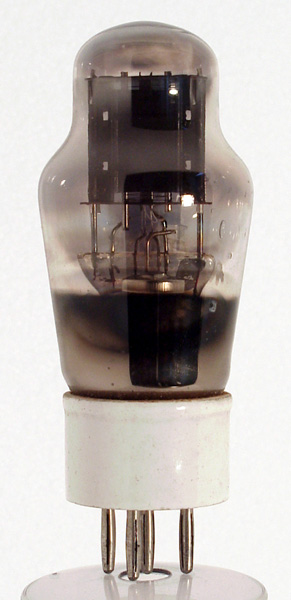
The VT designation was pre-WWII RAF code for a transmitting valve.In the picture can be seen the indirectly heated cathode, grid and anode.In the collection a pair of these triodes are in situ on a cavity oscillator.This valve is an M-OV Type ML6, which is essentially an ML4 with a 6 V heater and a ceramic base cap. The ceramic base is fitted in order to reduce oscillator drift due to hygroscopic variations with temperature and altitude that are possible with the normal black bakelite base cap.The original Type ML4 was designed as a receiving valve for operation with negative bias on the grid. When used as an HF oscillator the valve draws appreciable grid current at the peak of each cycle. One result of this is extra stress on the cathode, resulting in a certain amount of sputtering in the grid-cathode region. This has resulted in the (patterned) internal blackening of the envelope. Such blackening is often seen in valves (including HT rectifiers) used without enough negative bias to maintain a protective space-charge 'cushion' around the cathode surface. In general, power valves should not be used without negative bias unless specifically designed for operation in the grid current region.G3JLZ reports: the VT105 was used in the master oscillator of transmitter type T1154.The classic envelope is 42 mm in diameter and, excluding the B4 base pins, is 98 mm tall.References: Data-sheet & 1043. |
Pin Connections
| 1 | 2 | 3 | 4 | 5 |  a | g1 | h | h | k |
|
|
Absolute Maximum Operating Conditions
| Vh | Ah | Va | Vg | mAa | ra | gm | Pout | 
| 6.3 | 0.7 | 250 | -13.5 | 25 | 3,700 | 3.8 | 0.65W |
|
Updated July 11, 2016.
|
|