The LS6A, originally produced in 1929, was capable of an audio output of 5.0 Watts. The LS6A has a 25 Watt dissipation anode and so in Class A one would have expected 7 - 8 Watts and in AB1 or B considerably more, perhaps up to 20 Watts. The LS6A was the valve that was developed into the PX25.
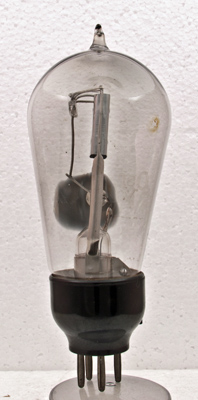
The original LS6A design uses a thoriated tungsten filament. This exhibit shows the characteristic orange glow when operating. At 6.0 Volts this example takes 2.0 Amps. Although all LS6A's are supposed to be thoriated tungsten based we have a later example LS6A that has an oxide coated filament.
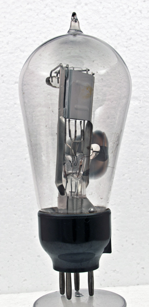
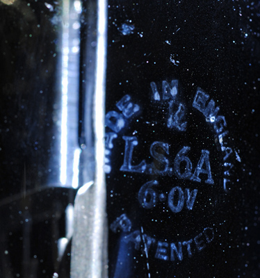
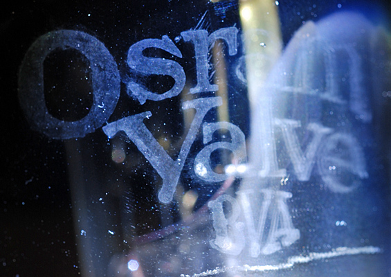
The glass is etched in two places, one site features the words Osram Valve and BVA whilst the second area is circular with made in England around the outside and LS6A and 6.0V within. This exhibit has the evacuation pip at the top of the bulb, later production had a smooth dome and was evacuated through the stem.
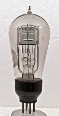
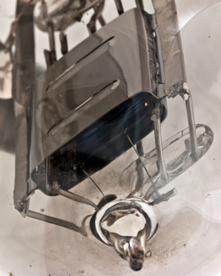
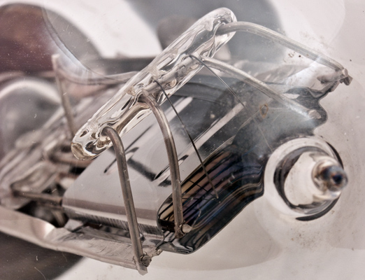
The anode is bright and a glass bead is used to hold the filament top springs.The use of mica sheets to hold electrodes in place occurs in later valve designs.
Side view.
Full face view.
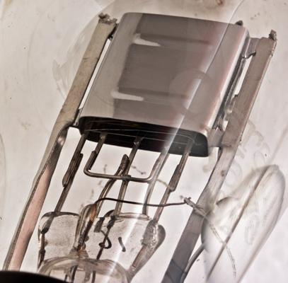
The pinch and lower electrodes. The filament is M shaped and the two sections are connected in parallel.
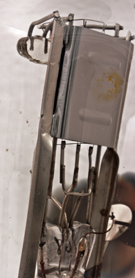
The top of the anode showing the filament loops held in cupped springs.
Greater detail of the top of the anode. The filament shape is clear as is the grid construction.
With dark field illumination the faint etched lettering is revealed as are the imperfections in the bulb glass.
Another dark field shot. Again etched lettering. The lettering covers a significant part of the glass and thus it is difficult to get it all in focus at the same time.
The balloon envelope is 62 mm in diameter, and excluding the B4 base pins is 139 mm tall.
References: Data-sheet. Type LS6A was first introduced in 1929. See also1929 adverts.