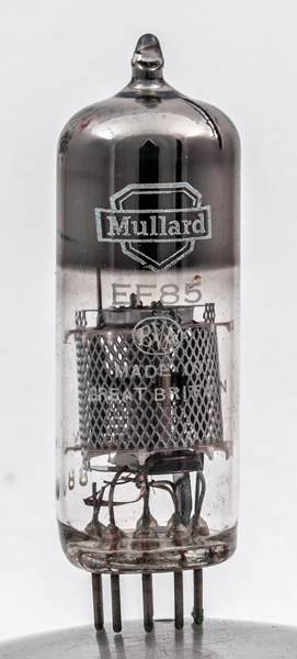
The EF85 is a VHF variable μ pentode and is the counterpart to the EF80 straight RF pentode. Clearly this places the valve in a superhet context with AGC applied to the RF and IF sections. At the time it was designed television receivers operated on Band I at about 50 MHz and from 1955 also on Band III at around 175 MHz. The EF183, released in the 1960s, overtook its performance just as the EF184 replaced the EF80.
The EF85 was tasked with IF amplification in VHF/AM radio receivers.
When Band IV and Band V UHF television entered service in the early to mid 1960's the front end required specialised triodes to operate at 400 - 850 MHz.
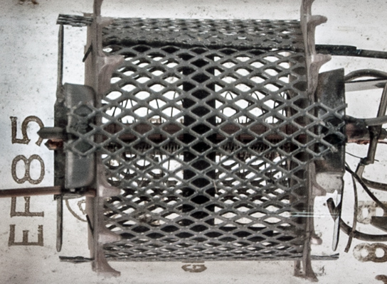
The anode consists of two small plates joined by a strap.
This image shows the three grids within the screen cylinder. The control grid passes flat across the cathode.
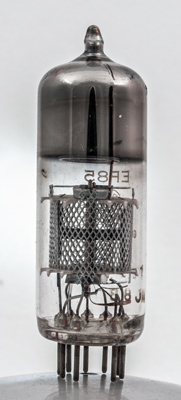
The thin glass tube envelope is 20 mm in diameter and, excluding the B9A base pins, is 59 mm tall.
References: Data-sheet & 1040. Type EF85 was first introduced in 1951. See also1951 adverts.