|
ECH81Sensibly equivalent¶ to:See also:
|
|
|
|
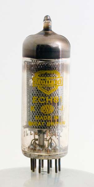
The ECH81 triode heptode was designed in 1954 for the role of frequency changer (mixer) in superhet receivers for AM reception. The ECH81 acting as oscillator and mixer for AM and the heptode being the first IF amplifier on FM.The two valve sections share a common cathode. The triode is to be used as the local oscillator feeding the 13 Volts amplitude sine wave to the heptode mixer. Within the heptode, non linear operating causes the signals to interact to produce in the anode waveform the following major frequencies: signal, LO, signal + LO and signal minus LO. The anode circuit is tuned to enhance one of these signals, normally signal minus LO. For radio reception at the time an intermediate frequency of 455 KHz would be typical for AM.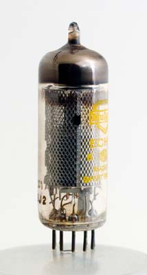
From the side, through the screen, can be seen two sizes of electrodes. Under a glass the lower section can be seen to contain several wire grid spirals. Above the main assembly the cathode continues and a single grid can be seen. Thus the triode is mounted above the mixer on the common cathode tube.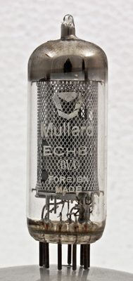
Another ECH81 from the collection. Here the later stylised logo is used and the manufacture is not in the UK.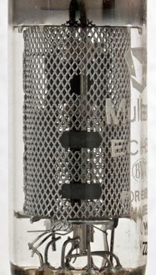
Looking into the screen the wire grids can be seen. The anode is only fully present in the plane parallel to the cathode. 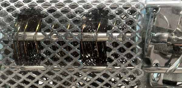
An enhanced view of the outer grids.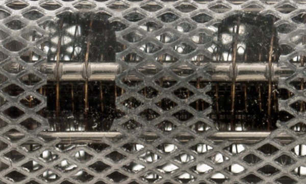
Here the notch and peening method of securing the grid wire can be plainly seen in the outermost grid.The thin glass tube envelope is 20 mm in diameter and, excluding the B9A base pins, is 55 mm tall.References: 4051 & 1040. Type ECH81 was first introduced in 1953. See also 1953 adverts. |
Pin Connections
| 1 | 2 | 3 | 4 | 5 | 6 | 7 | 8 | 9 |  g2,g4 | g1 | k,g5,s | h | h | a | g3 | a(t) | g1(t) |
|
|
Absolute Maximum Operating Conditions
| Vh | Ah | Va | mAa | 
| 6.3 | 0.3 | 100 | 13 |
|
Absolute Maximum Operating Conditions
| Va | Vs | Vg | mAa | mAs | ra | gm |
| 250 | 250 | -2 | 6.5 | 3.8 | 0.7M | 0.775 |
|
Updated October 12, 2016.
|
|