|
PFL200Sensibly equivalent¶ to:16Y9See also:
|
|
|
|
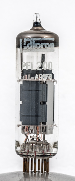
The PFL200 valve contains two separate pentode valves in one package. For consumer electronics products cost reduction was vital, and the more functionality within each envelope the better.The first (the 'F' pentode) is a low power low voltage type with all three grids visible, and the second is a power pentode, probably a beam tetrode from visual observations. To accommodate a pair of pentodes Mullard, the original designers, introduced a 10 pin base - the B10B.One particular function of this valve was within colour television receivers. One pentode would drive the CRT cathode, while the other would be employed as part of the colour difference circuitry. Each of the three guns of the shadow mask tube would use one of these valves.The PFL200 also found service in monochrome receivers. The output pentode was used for the video amplifier to drive the picture tube cathode, while the the amplifier pentode was employed as a sync separator.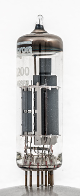
The voltage amplifier pentode is on the left with the power valve on the right.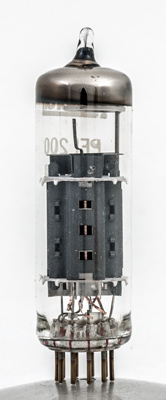
The power valve is constructed as a beam tetrode. The beam plate is just visible inside the anode.
A closer view of the voltage amplifier. All three grids can be seen through the hole in the anode end wall.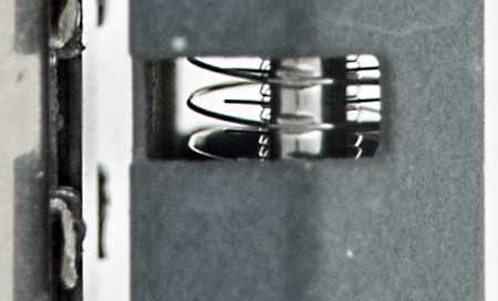
An enlargement of the detail of the grids.The thin glass tube envelope is 21 mm in diameter and, excluding the B10B base pins, is 68 mm tall.References: Data-sheet & 1040. Type PFL200 was first introduced in 1964. See also 1964 adverts. |
Pin Connections
| 1 | 2 | 3 | 4 | 5 | 6 | 7 | 8 | 9 | 10 |  g1(2) | k,g3(2) | g2(2) | a(2) | h | h | k,g3,s(1) | g1(1) | g2(1) | a(1) |
|
|
Absolute Maximum Operating Conditions
| Vh | Ah | Va | Vs | Vg | mAa | mAs | ra | gm | 
| 16.5 | 0.3 | 170 | 170 | -2.6 | 30 | 6.5 | 40k | 21 |
|
Absolute Maximum Operating Conditions
| Va | Vs | Vg | mAa | mAs | ra | gm |
| 150 | 150 | -2.3 | 10 | 3 | 160k | 8.5 |
|
Updated January 03, 2019.
|
|