|
ECF80Sensibly equivalent¶ to:See also:
|
|
|
|
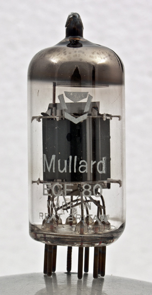
This ECF80 from Mullard differs from ECF80 in having white lettering and the later logo.Mullard say that the ECF80 was designed for mixer operation up to 220 MHz. As 1950s television receivers tended to use the PCFnn 300 mA valves, the production of this valve with a 6.3 Volt heater suggests that it was aimed at the professional VHF communications market.The triode is the oscillator and has to produce 5 V pk-pk signal. The screened pentode is the mixer. The valve has two cathodes so two independent valves are sited in the one envelope.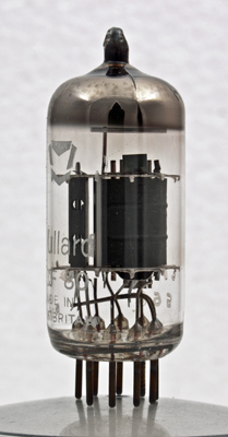
The triode on the left with grid visible through the hole in the end wall of the anode. he pentode is oriented at 90 degrees to the triode.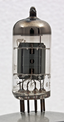
The pentode looking along the line plane of the grids. The suppressor grid support can be seen through the holes in the end of the anode.The thin glass tube envelope is 20 mm in diameter and, excluding the B9A base pins, is 48 mm tall.References: Data-sheet & 1040 Type ECF80 was first introduced in 1954. See also 1954 adverts. |
Pin Connections
| 1 | 2 | 3 | 4 | 5 | 6 | 7 | 8 | 9 |  a(t) | g1 | g2 | h | h | a | k,s,g3 | k(t) | g1(t) |
|
|
Absolute Maximum Operating Conditions
| Vh | Ah | Va | Vs | Vg | mAa | mAs | ra | gm | 
| 6.3 | 0.43 | 250 | 180 | -5.8 | 5.7 | 1.4 | 1.5M | 2.1 |
|
Absolute Maximum Operating Conditions
| Va | Vg | mAa | ra | gm |
| 100 | -2 | 14 | 4K | 5 |
|
PDF scanned from an original document held by the museum |
Updated March 08, 2020.
|
|