|
Half Way Between Ordinary Electrode Structures and Disc-Seal Techniques
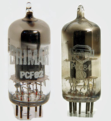
New valves for Band III television tuners. On the left the 9U8/PCF82 triode-pentode frequency changer and on the right the PCC84/7AN7 double-triode cascode RF amplifier.
Receiving valves for Bands III, IV and V generally differ from those used in lower frequency bands because it is essential for the RF mixer and IF stages to give more gain in order to achieve a similar signal-to-noise ratio. Television receivers for Band I generally have an IF not exceeding 20 MHz, a pentode mixer and a single pentode RF stage, and a signal-to-noise ratio between 6 and 8 db is achieved in good designs. This figure may not be obtained, however, on all channels in Band I unless a modern type of RF pentode is used. Earlier types of RF pentode such as the 8D3, 6F12, Z77 and EF91 developed during the war have a single cathode connection, with the result that their input impedance is about 8.9 kΩ at 45 MHz but only 3.8 kΩ at 67 MHz. This value is below the critical damping necessary for the bandwidth required, so the gain is lower and the noise worse for Channel III than for Channel I.
Modern RF pentodes such as the 6BW7, 6BX6 and EF80 have two separate connections from the actual cathode to the circuit, one being used for the input circuit and the other for the output circuit. This avoids a common cathode impedance in both circuits (inductance of the single lead) which normally couples them together and has the effect of lowering the impedance of the input circuit. As a result of this technique the input impedance of the 6BW7, for example, is 18kΩ at 45 MHz and 6.5 kΩ at 67 MHz. These figures are twice as high as those of the earlier types.
Current television receivers designed for use on both Bands I and III use a higher IF usually around 34-35 MHz, and the improved input impedance or modern RF pentodes is desirable here also. This is because it is not a good thing for the circuit damping (necessary for bandwidth requirements), to be provided wholly by the valve, since replacing a valve could change appreciably the IF response characteristics.
These points are mentioned because the use of multiple connections is a feature of valves designed for the higher frequencies, although such connections are not necessarily always to the cathode.
The front end of receivers for Bands I and III usually takes the form of a multiple-position tuner comprising an RF stage and a mixer/oscillator, the tuned circuits being switched by ganged switches and rotated on a turret. In order to conserve space and obtain improved performance new mixers have been designed, and these are generally triode pentodes. Typical examples are the 6U8/ECF82 and ECF80 with their AC/DC versions 9U8/PCF82 and PCF80. These valves have much higher triode and pentode slopes than the types of triode pentode with which we are familiar. The 6U8, for example, has a triode slope of 8.5 mA/V and a pentode slope of 5.2 mA/V. The high triode slope ensures ready oscillation an the high pentode slope good conversion conductance as a mixer. Apart from the heater the two units are quite separate and this tends to reduce the possibility of oscillator radiation via the mixer portion.
The RF stage for such tuners does not use an RF pentode but a double triode in a 'cascode' circuit. Triodes will always give lower noise than pentodes because of what is known as partition noise. The cathode current of a pentode comprises two portions, the anode current and the screen current, and both contribute to the noise but only the anode current to the useful signal. A pentode has, as a first approximation, three times the noise it would have if used connected as a triode. There are, of course, some snags in using triodes as RF amplifiers and they normally need to be neutralized in order to achieve stability. The cascode system is a trick which creates a stable circuit from two triodes.
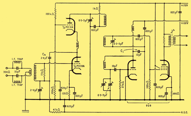
Circuit of typical television tuner for Bands I and III using the two new valves shown at the top of the page.
The diagram above shows a typical tuner circuit for Bands I and III. The lower triode of the first valve is used with an earthed cathode and the upper one with an earthed grid. The lower section has a fairly high input impedance but gives little gain except for the step up in the input transformer because it is working into the cathode impedance of the other section, which is very low. This upper section gives quite a good gain and the overall result is a gain from the aerial input to the mixer grid of about ten times (23 dB). There is often a small coil between the anode of the first triode and the cathode of the second one, and this is for peaking the frequency characteristic of the circuit above 200 MHz to improve the gain. A small neutralizing capacitor is connected from the anode of the first section to the series-tuned grid circuit; this is not primarily for the purpose of obtaining stability but for improving the signal-to-noise ratio. Valves suitable for this circuit are the PCC84/7AN7, 6BQ7A, 6BK7A and 6BZ7; these give a noise ratio of about 7 dB.
The mixer circuit is conventional except that a negative temperature coefficient capacitor C1 is required across the oscillator tuned circuit, otherwise the frequency drift is excessive. The maximum drift on Band III allowable in this country is rather less than in the USA and on the Continent because we use AM sound as against inter-channel FM a proposed BREMA figure is 50 kHz maximum.
Conventional British multi-channel tuners use very tiny coils for the circuits; some, in fact, are just straps across adjacent switch contacts. Their Q is, therefore, poor and so is the L/C ratio, the C being mainly valve capacitance and strays. As a result the frequency stability is not very good.
Oscillator Drift Problem
One possible approach to the oscillator drift problem is exemplified in a Band III to Band I converter designed by the author. The oscillator uses a trough tuned line, electron-coupled oscillator fashion. The triode grid is tapped two-thirds of the way up the line and the cathode one-third of the way up, the heater lead being taken back inside the line. The two tuning capacitors, one variable (band-spread) and one fixed (band-set), are across the hot end of the line and the mixer is coupled to the oscillator cathode. Such a tuned circuit has a drift of 20 kHz from cold and a drift of 100 Hz per volt for HT variations. Lines of this type need not be of any particular shape or size and can be bent, and if they are not required to be continuously tuned the capacitors can be switched in discrete steps. The author has used this type of tuned circuit for years in a receiver covering both the 2-metre amateur band and the 90-MHz FM band, and in fact it is not difficult to arrange this form of circuit to cover a frequency range of 3 to 1.
Valves for Bands IV and V require higher slopes and lower noise factors than for Band III. This can only be achieved by closer electrode spacing and multiple connections to the essential electrodes. An example of such a valve is the 6AM4 which is an earthed-grid RF amplifier or mixer for use up to 1,000 MHz. Since the common electrode is the grid this uses five separate grid connections. In order to reduce the lead inductance the structure is mounted horizontally right down on the glass base. The slope of the valve is 9.8 mA/V.
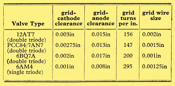
Critical dimensions in UHF and VHF triodes
The above table gives some idea of the increased difficulties of manufacture resulting from attempting to obtain similar performance at higher and higher frequencies. A quite modern type, the 12AT7, is given for comparison purposes.
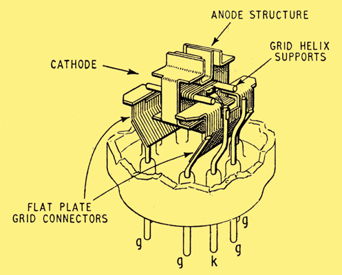
Electrode structure of the 6AM4 triode, intended for earthed-grid operation up to 1,000 MHz. The grid is connected to five base pins (one not shown) through two flat metal sheets, which not only provide a low-inductance path to earth but shield the cathode and heater connectors from the anode. Flat strip is also used for the anode and cathode connectors.
The 6AM4 has a grid cathode clearance of only one-thousandth of an inch and the grid is wound with 1< thou' wire with a gap of two thou's between turns. The reduction of grid-cathode spacing is necessary in order to maintain the required value of mutual conductance, and the grid-anode spacing has to be similarly reduced to keep the amplification factor in proportion. More turns per inch and thinner wire on the grid helix are an outcome of the generally smaller electrode structure. The valve will give a noise factor of about 6 dB as an RF amplifier in Band IV and about 9 db as a mixer, and the diagram below shows a circuit including both these applications.
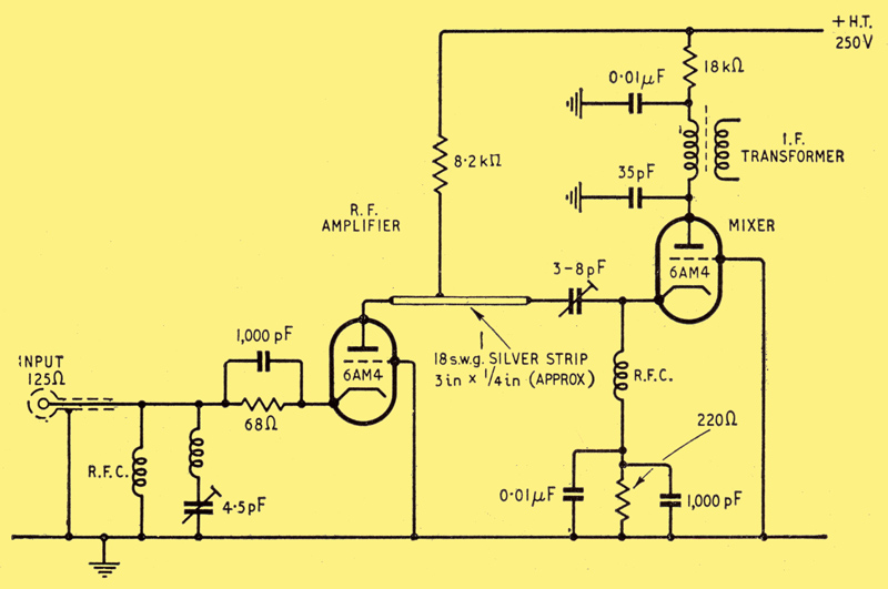
The 6AM4 triode used as an RF amplifier and as a mixer in a Band IV receiving circuit (70 cm). The oscillator (not shown) is coupled inductively to the silver-strip line.
The corresponding oscillator valve is the 6AF4, which has a slope of 6.6 mA/V. It has two grid connections and three anode connections, as it is normally used with the cathode choked and the grid or anode earthed. More expensive valves, because of their construction, are the disc-seal types also known as lighthouse, planar, pencil or rocket valves. The grid, anode and, in the case of tetrodes, screen grid are brought out to discs or rings which can be clamped into the circuit and thereby provide a continuous and therefore infinite number of connections. These give even better performances than normal valves but in their present form are unlikely to be used in Bands IV and V for domestic television.
Crystal Mixture
A type of mixer commonly used for these bands is the crystal mixer, the most popular being the silicon type although germanium ones are also available. These mixers are somewhat critical of heterodyne voltage and give a conversion loss of about 6 dB. A converter can be made for Band IV with a noise factor of about 7 dB if considerable care is taken. This figure can only be achieved if the first stage of the IF amplifier has very low noise, and this is usually obtained by using a cascode or neutralized triode for the first IF stage. It is also essential that the heterodyne voltage is free from noise and spurious frequencies. Since the noise output from the crystal is proportional to the crystal current generated by the applied heterodyne voltage, the presence of anything other than the frequency required (± a few cycles ideally) merely increases the noise without improving the signal. This is one effect responsible for poor noise figures in crystal mixers, particularly when the oscillator is operating at harmonic frequency or is generated by a lower frequency crystal, but it can be reduced by the insertion of a sharp filter or high-Q break between the heterodyne source and the mixer.
On all high frequency bands care must be exercised in the coupling between stages, particularly that between the aerial feeders and the first stage, and it should be remembered that the coupling that gives the maximum gain rarely gives the best signal-to-noise ratio: The lowest noise is usually obtained when the coupling is tighter than that required for normal gain.
Mention: was made earlier of the importance of a low-noise RF stage to reduce the effect of mixer noise, and here it is worth noting the effect on noise factor of adding RF stages in front of a receiver in Band IV. With a noise factor about 6 dB in the receiver, the addition of a disc-seal pre-amplifier of 20 dB gain reduces this to 3 dB while a further pre-amplifier brings it down to 2 dB.
This article is based on a lecture recently given by the author to the Television Society.
|