|
PFL200Sensibly equivalent¶ to:16Y9See also:
|
|
|
|
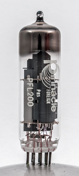
The PFL200 combines a screened amplifier pentode and an output pentode in the one envelope. It was designed for television use, but probably not for audio output as the operating conditions do not give an output power. The mutual conductance of the output pentode at 21 is very high, pointing to a very small space between cathode and control grid.The valve was used for video output in colour television receivers. Three would be used per receiver, one per gun. The second pentode would be used in the colour difference circuitry. The presence of the internal screen points to the video usage.When used in monochrome receivers the valve was used for video output and the low power pentode as a sync pulse separator.The B10B base was a late introduction, near the end of the use of valves in consumer products. By putting two pentodes in a single envelope the price would have been lower for set manufacturers in overall assembly costs.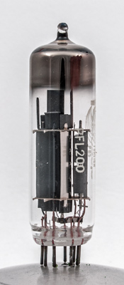
The voltage amplifier pentode on the right is little larger than a triode would be in a triode pentode.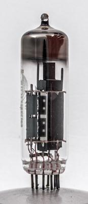
The power pentode has a radiating fin on the top of the control grid above the top mica. The bright screen can be seen in the centre.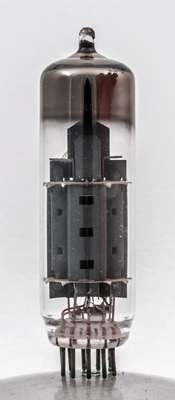
Looking along the axis of the main pentode. The two right angle fins connect to the screen.The thin glass tube envelope is 21 mm in diameter and, excluding the B10B base pins, is 70 mm tall.References: Data-sheet & 1040. Type PFL200 was first introduced in 1964. See also 1964 adverts. |
Pin Connections
| 1 | 2 | 3 | 4 | 5 | 6 | 7 | 8 | 9 | 10 |  g1(2) | k(2),g3(2) | g2(2) | a(2) | h | h | k(1),g3(1),s | g1(1) | g2(1) | a(1) |
|
|
Absolute Maximum Operating Conditions
| Vh | Ah | Va | Vs | Vg | mAa | mAs | ra | gm | 
| 16.5 | 0.3 | 150 | 150 | -2.3 | 10.0 | 3.0 | 0.16M | 8.5 |
|
Absolute Maximum Operating Conditions
| Va | Vs | Vg | mAa | mAs | ra | gm |
| 170 | 170 | -2.6 | 30.0 | 6.5 | 40,000 | 21.0 |
|
Updated January 03, 2019.
|
|